A reliable fire protection system depends on more than the performance of the fire pump itself. It also requires an effective control system that monitors operating conditions, starts the pump when needed, and provides essential information about its status. One of the most important components in this process is the fire pump controller.
For building owners, fire protection engineers, system integrators, contractors, and facility managers, understanding how a fire pump controller works is essential when selecting, installing, commissioning, and maintaining a fire pump system.
A properly selected controller helps ensure that the fire pump is ready to operate during an emergency. It coordinates starting and stopping functions, monitors important operating conditions, and provides alarms or status indications that support system supervision.
In this article, we explain what a fire pump controller is, how it works, the main types available, the differences between electric and diesel fire pump controllers, and the key factors to consider when selecting a controller for a fire protection project.
A fire pump controller is an electrical control device designed to manage the operation of a fire pump in a fire protection system. Its primary purpose is to start the fire pump when required, monitor its operating status, and provide the controls and indications necessary for reliable operation.
In a typical automatic fire protection system, water pressure is maintained within a designated range. When the pressure drops because sprinklers activate, a hydrant system is used, or another demand occurs, the fire pump controller can initiate the starting sequence according to its configured settings and the applicable requirements.
The controller is therefore an essential interface between the fire pump, its driving equipment, and the fire protection system.
A fire pump controller commonly includes several major components:
Control logic: Processes pressure signals, manual commands, and other inputs to determine when the pump should start.
Starting equipment: Provides the necessary starting control for an electric motor or diesel engine.
Monitoring devices: Monitor relevant conditions, such as power availability, controller status, and engine operating parameters, depending on the controller type.
Alarm and indication functions: Display operating conditions, faults, and other important information.
Manual controls: Allow authorized personnel to perform required operating and testing procedures.
The exact configuration depends on the type of fire pump, the drive system, the controller model, and the applicable fire protection standards.
It is important to distinguish a fire pump controller from a general-purpose industrial motor control panel. A fire pump controller is specifically designed for fire protection applications, where starting reliability and continued operation during an emergency are critical.
The operating principle of a fire pump controller is relatively straightforward: it receives information about the fire protection system, determines when the pump must start, and controls the starting process.
However, the details vary depending on whether the fire pump is driven by an electric motor or a diesel engine.
In an automatic fire protection system, a pressure-sensing device monitors the pressure in the fire protection piping or another designated sensing point.
When the system is in its normal standby condition, pressure remains within the expected operating range. The controller monitors the configured starting conditions through the appropriate sensing arrangement.
If water demand increases and the pressure falls below the designated start threshold, the controller receives the corresponding signal.
Pressure settings must be established according to the system design, pump arrangement, and applicable requirements. Incorrect settings can cause unnecessary starts or delay the intended starting response.
When the required starting condition is detected, the controller initiates the pump's starting sequence.
For an electric fire pump, the controller operates the appropriate motor-starting equipment. Depending on the design, this may involve across-the-line starting or another permitted starting method.
For a diesel engine fire pump, the controller activates the engine-starting system, which typically uses batteries and an electric starter.
The starting method must be compatible with the selected motor or engine and the requirements governing the fire pump installation.
After the pump starts, the controller provides status indications appropriate to its design.
An electric fire pump controller may indicate that the motor is running, that power is available, or that a monitored electrical condition requires attention.
A diesel fire pump controller may display engine-running status and provide indications for conditions such as low oil pressure, high coolant temperature, or battery-related problems, depending on the equipment configuration.
These indications help operators understand the condition of the fire pump system. They do not replace the need to verify actual pump performance, water flow, and discharge pressure during commissioning and testing.
Once a fire pump has started in response to a fire protection demand, its controller must operate according to the applicable requirements and the system's approved design.
Unlike many ordinary industrial motor systems, a fire pump installation must not rely on a conventional automatic stop strategy that could interrupt necessary fire protection service.
Depending on the applicable standard and controller configuration, the pump may require manual stopping after the demand has ended. Automatic stopping, where permitted, must follow the relevant requirements and approved system design.
The controller's role is to support the required operation of the fire pump, not to make assumptions about whether a fire emergency has ended.
During operation, the controller may indicate abnormal conditions and alert personnel to issues requiring investigation.
Examples include loss of normal power, failure to start, engine faults, and other monitored conditions.
The specific alarms available depend on the controller type. Alarm indications help maintenance teams identify potential problems, but an alarm does not always mean the pump has completely stopped working.
Understanding the meaning of each indication is important for troubleshooting and maintaining system readiness.
Fire pump controllers are available in several configurations to suit different fire pump drives and project requirements.
Electric fire pump controllers are designed to start and control fire pumps driven by electric motors.
They commonly include power monitoring, motor-starting equipment, operating status indications, and control functions for automatic or manual starting.
Depending on the motor rating and controller design, starting methods may include across-the-line starting, reduced-voltage starting, or other methods permitted for the application.
When selecting an electric fire pump controller, engineers should consider the motor power, rated voltage, frequency, starting current, available power supply, and the requirements of the applicable fire protection standard.
The controller must be correctly matched to the motor and the intended fire pump duty.
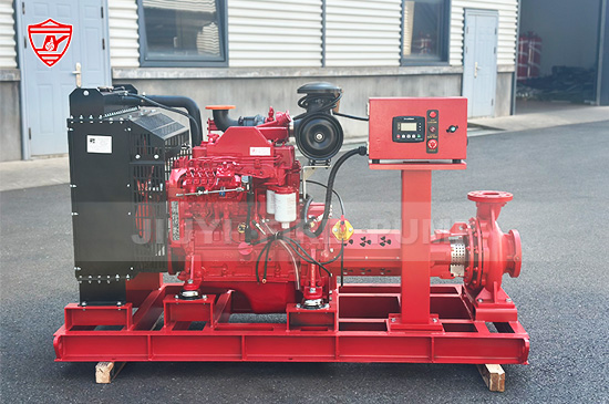
Diesel fire pump controllers are designed to start and monitor fire pumps driven by diesel engines.
They typically manage automatic engine starting, starter operation, battery-related functions, and selected engine monitoring signals.
Many configurations include dual battery sets and associated starting circuits to support the required starting reliability. The exact arrangement depends on the engine package, controller design, and applicable requirements.
Diesel fire pump controllers are particularly important where an independent engine-driven pumping option is required, such as installations that use both electric and diesel fire pumps.
Because diesel engines have additional mechanical and electrical operating requirements, their controllers differ significantly from electric motor controllers.
A jockey pump is a small pressure-maintenance pump used to compensate for minor leakage and normal pressure fluctuations in a fire protection system.
Its controller maintains the pressure within the designated range by starting and stopping the jockey pump according to configured pressure settings.
The jockey pump helps reduce unnecessary starts of the main fire pump caused by small pressure losses. It does not replace the main fire pump or provide the primary firefighting water supply.
Jockey pump control settings must be coordinated with the main fire pump start settings so that the jockey pump does not delay the required operation of the main fire pump.
Some fire pump installations include electric main pumps, diesel standby pumps, and jockey pumps. Each pump may have its own dedicated controller, depending on the system design.
These controllers work within the same fire protection arrangement but perform different functions.
For example, an electric main pump controller manages the electric motor, while a diesel controller manages the engine-driven pump. The jockey pump controller maintains system pressure during normal standby conditions.
The overall sequence must be coordinated through appropriate system design and control settings. Multiple controllers should not be assumed to operate as a single integrated controller unless the equipment is specifically designed for that arrangement.
The primary difference lies in the equipment being controlled.
|
Feature |
Electric Fire Pump Controller |
Diesel Fire Pump Controller |
|---|---|---|
|
Drive equipment |
Electric motor |
Diesel engine |
|
Starting method |
Electrical motor-starting circuit |
Battery-powered starter system |
|
Main monitoring functions |
Power supply, motor operation, and relevant electrical conditions |
Engine operation, batteries, and relevant engine conditions |
|
Typical maintenance focus |
Electrical connections, power supply, and starting equipment |
Batteries, starter circuits, engine monitoring, and related equipment |
|
Key selection factors |
Voltage, frequency, motor rating, and starting method |
Engine compatibility, battery arrangement, and starting requirements |
Both types are designed to support reliable fire pump operation, but they require different engineering considerations.
An electric controller must be compatible with the motor and electrical supply. A diesel controller must be compatible with the engine and its starting and monitoring systems.
The correct selection depends on the fire protection system design, the available utilities, the required pump configuration, and the applicable standards.
A fire pump controller is essential because it supports the timely operation and supervision of equipment intended for emergency use.
Automatic starting allows the fire pump to respond to a designated starting condition without waiting for an operator to activate it manually.
This is particularly important in buildings, industrial facilities, warehouses, ports, and petrochemical installations, where a fire may develop when personnel are not immediately available to operate the equipment.
Controller indications help operators identify power problems, starting issues, and other abnormal conditions.
This information supports maintenance planning and helps personnel investigate problems before the equipment is needed in an emergency.
The controller is one part of a larger system that includes the pump, driver, water supply, piping, valves, and associated monitoring equipment.
Reliable fire protection requires these components to be correctly selected, installed, tested, and maintained as a complete system.
Appropriate controller functions and status indications support routine inspection, operational testing, and troubleshooting.
When combined with documented test procedures and qualified maintenance personnel, they help establish whether the fire pump installation remains ready for service.
Choosing a suitable controller requires more than matching its nominal rating to the fire pump. Several technical and project-specific factors should be evaluated.
1. Identify the drive type. Determine whether the fire pump uses an electric motor or diesel engine. The controller must be designed for the corresponding drive system.
2. Confirm the equipment ratings. For electric systems, check the motor power, voltage, frequency, phase, and starting requirements. For diesel systems, verify engine compatibility, starting arrangements, and relevant monitoring requirements.
3. Check the applicable standards. NFPA 20 is a widely referenced standard for the installation of stationary pumps for fire protection. Projects may also be subject to local codes, authority requirements, and specified product approval requirements. Confirm the applicable edition and project requirements before selecting the equipment.
4. Verify certification and approval requirements. Some projects specify controllers listed by UL or approved by FM. These designations are not interchangeable, and the required status should be verified for the exact controller model and intended application.
5. Evaluate the operating environment. Consider ambient temperature, humidity, dust, vibration, electrical conditions, and the installation location. Industrial and outdoor applications may require particular enclosure and environmental protection arrangements.
6. Review monitoring and alarm requirements. Identify the indications, contacts, and remote monitoring interfaces required by the project. Ensure that the controller can provide the necessary information without compromising its primary fire pump control functions.
7. Confirm compatibility with the complete pump package. The controller, driver, pump, sensors, and associated components must work together as intended. Reviewing the complete equipment configuration before procurement can reduce integration problems during installation and commissioning.
Even a properly selected controller requires inspection and maintenance. Understanding common problems helps project teams investigate faults systematically.
Possible causes include incorrect pressure settings, a problem with the pressure-sensing line, a faulty sensing device, an electrical supply issue, or a problem in the starting circuit.
For diesel systems, battery condition and starter circuit performance may also be relevant.
Troubleshooting should begin by checking controller indications and following the manufacturer's approved procedure. Any test must be performed by qualified personnel without compromising the availability of required fire protection.
Frequent starts may be associated with system leakage, pressure fluctuations, incorrect pressure settings, or an improperly configured jockey pump.
The investigation should consider the complete pressure-maintenance arrangement rather than focusing only on the main pump controller.
An alarm may indicate an abnormal power condition, starting problem, engine condition, or another monitored fault.
Personnel should identify the specific alarm, consult the controller documentation, and investigate the underlying cause. Resetting an alarm without understanding the reason may leave an important problem unresolved.
For an electric controller, possible causes include an unavailable power supply, an open circuit, a protective device issue, or a fault in the indication circuit.
For diesel controllers, the relevant checks may involve the controller supply, battery circuits, or associated connections.
Electrical work and engine-related troubleshooting should be performed by qualified personnel following appropriate safety procedures.
Regular inspection and testing help ensure that a fire pump controller remains capable of performing its intended functions.
A suitable maintenance program should be based on the applicable standards, manufacturer instructions, local regulations, and the facility's approved procedures.
Key activities may include:
Inspecting the controller enclosure for damage, corrosion, moisture, or other environmental problems.
Checking available power sources and relevant electrical connections.
Verifying controller indications and monitoring functions.
Testing automatic starting and other required operating sequences under approved conditions.
Inspecting diesel engine starting batteries and associated circuits where applicable.
Reviewing alarms, event records, and maintenance documentation when supported by the equipment.
Recording test results and addressing any identified deficiencies.
Testing must be planned so that the fire protection system remains appropriately supervised and available. Personnel should not disable critical functions or perform unauthorized adjustments simply to clear an alarm.
For projects requiring listed or approved equipment, maintenance and replacement components should also be checked against the applicable product and installation requirements.
A fire pump controller cannot compensate for an incorrectly selected pump, inadequate water supply, unsuitable driver, or poorly designed piping system.
The performance of a fire pump installation depends on the coordination of all major components.
For example, a fire pump used in a warehouse must be selected according to the hydraulic requirements of the fire protection system. Its controller must be compatible with the selected driver and configured to respond to the intended starting conditions.
In a petrochemical facility or port terminal, additional project considerations may include environmental conditions, equipment accessibility, monitoring interfaces, and specific approval requirements.
For residential and commercial buildings, coordination between the main fire pump, jockey pump, pressure-sensing arrangements, and associated control equipment is equally important.
A complete fire pump package should therefore be evaluated as an integrated engineering solution rather than as a collection of independent products.
Manufacturers and project engineers should work together to verify equipment ratings, control functions, interfaces, and testing requirements before delivery and commissioning.
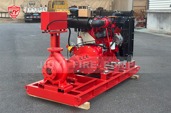
A fire pump controller is a critical component of a fire protection system. It manages the required starting functions, monitors operating conditions, and provides essential status and alarm indications to support the reliable operation of electric and diesel fire pumps.
Understanding how a fire pump controller works helps engineers, contractors, system integrators, and facility managers make better decisions about equipment selection, system design, commissioning, and maintenance.
The right controller must be compatible with the pump driver, match the project's electrical and operating requirements, and comply with the applicable standards and approval specifications. Equally important is the correct integration of the controller with the pump, water supply, pressure-sensing devices, and other system components.