A fire pump controller is an electrical or electronic device that automatically starts and monitors a fire pump when system pressure drops below a set threshold. Unlike standard pump controls, fire pump controllers are designed for reliability and must start under all conditions, even during adverse situations.
According to NFPA 20, fire pump controllers must prioritize starting the pump over preventing damage. This means the system will continue running even if abnormal conditions occur, such as overload or low suction pressure.
Fire pump controllers are typically used with:
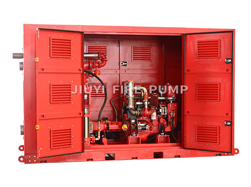
Electric motor-driven fire pumps
Diesel engine-driven fire pumps
Jockey pumps for pressure maintenance
Each type has its own control logic, but all follow a coordinated start sequence.
The start sequence logic defines how and when each component in the fire pump system operates. This is essential for several reasons:
1. Immediate Response to Fire Demand
The system must start automatically when pressure drops, without human intervention.
2. Avoiding False Starts
Pressure fluctuations happen regularly in piping systems. The controller must distinguish between normal variations and actual fire demand.
3. System Coordination
Multiple pumps must work together in a defined order to prevent pressure surges or mechanical stress.
4. Compliance with NFPA 20
Improper sequencing can lead to system failure or non-compliance, which is unacceptable in fire protection.
Although configurations may vary depending on the project, the standard fire pump system typically includes a jockey pump, a main fire pump, and sometimes a standby pump. The sequence usually follows this order:
Under normal conditions, the system is pressurized, and no fire pumps are running. The jockey pump maintains pressure by compensating for small leaks or minor usage.
System pressure is stable
All fire pumps are idle
Controllers are in standby mode
When a fire occurs or a hydrant or sprinkler opens, system pressure begins to drop. Pressure switches or transducers detect this change.
The system typically uses multiple pressure setpoints:
Jockey pump start pressure
Main fire pump start pressure
Standby pump start pressure
Each level triggers a different response.
The first response to a slight pressure drop is the jockey pump.
Starts automatically at a higher pressure setting
Handles small system losses
Prevents unnecessary fire pump starts
If the pressure recovers quickly, the fire pump will not start.
If the pressure continues to drop and reaches the fire pump start setpoint, the main fire pump controller activates.
This is the critical point in the sequence.
The controller will:
Start the pump immediately
Ignore non-critical faults
Continue running regardless of pressure recovery
Unlike standard pumps, the fire pump does not stop automatically when pressure is restored. It must be stopped manually to ensure continuous fire protection.
In systems with redundancy, a standby pump (often diesel-driven) may start if:
The main pump fails to start
Pressure continues to drop after the main pump starts
The standby pump ensures system reliability in case of electrical failure or mechanical issues.
During operation, the controller provides status signals such as:
Pump running
Power failure
Phase reversal
Engine fault (for diesel pumps)
These alarms are transmitted to fire alarm panels or building management systems.
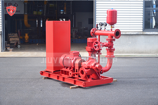
Electric fire pump controllers are commonly used due to their simplicity and reliability.
The controller starts the motor using one of the following methods:
Direct-on-line (DOL)
Star-delta starting
Soft starter
Variable frequency drive (VFD) (limited use in fire systems)
Pressure drops below setpoint
Pressure switch sends signal to controller
Controller energizes motor starter
Motor reaches full speed
Pump delivers rated flow and pressure
Once started, the controller will not stop the pump automatically, regardless of pressure recovery.
Automatic and manual start modes
Emergency manual start (mechanical)
Overcurrent monitoring (alarm only)
Phase failure and phase reversal protection
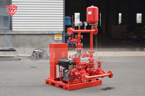
Diesel fire pumps are used when electrical power is unreliable or as backup systems.
Their start sequence is more complex due to engine requirements.
Pressure drops below setpoint
Controller initiates start signal
Engine cranks using batteries
Multiple crank attempts (typically up to 6)
Engine starts and reaches rated speed
If the engine fails to start, the controller generates alarms but continues attempting to start.
Once running, the diesel engine:
Maintains constant speed
Is not stopped automatically
Requires manual shutdown
Dual battery system
Battery charger monitoring
Fuel level monitoring
Engine temperature and oil pressure alarms
Diesel controllers are designed to ensure starting under any condition, even if some faults are present.
The correct setting of pressure switches is essential for proper sequence operation.
A typical arrangement is:
Jockey pump start: highest pressure (e.g., 145 psi)
Jockey pump stop: slightly higher (e.g., 150 psi)
Fire pump start: lower pressure (e.g., 130 psi)
Standby pump start: lowest pressure (e.g., 120 psi)
This staggered arrangement ensures:
Jockey pump handles minor losses
Fire pump starts only during real demand
Backup pump activates only when necessary
Improper settings can cause:
Frequent fire pump starts
Pressure instability
System wear and tear
Fire pump controllers must allow manual operation in case of automatic failure.
Operators can start the pump using:
Control panel buttons
Remote start signals
Controllers are equipped with mechanical means to start the pump even if electronics fail.
For electric pumps, this may involve:
Manual contactor operation
For diesel pumps:
Manual crank or override switch
This ensures the system can operate under any circumstance.
In real projects, improper logic design can lead to serious issues. Some common mistakes include:
Incorrect Pressure Settings
Poor coordination between jockey and fire pumps leads to unnecessary starts.
Lack of Time Delay
Without delays, the system may respond too quickly to minor pressure drops.
Improper Pump Sizing
Oversized pumps cause pressure spikes and instability.
Ignoring Redundancy
No standby pump can compromise system reliability.
Non-compliant Controllers
Controllers not meeting NFPA 20 or UL standards may fail inspections.
To ensure optimal performance and compliance, follow these best practices:
1. Follow NFPA 20 Requirements
Always design and configure controllers according to NFPA 20 guidelines.
2. Use UL Listed Controllers
UL listed equipment ensures safety and compliance.
3. Coordinate Pressure Settings Carefully
Maintain clear separation between jockey and fire pump start points.
4. Test Regularly
Perform weekly and monthly tests to verify operation.
5. Provide Redundancy
Use diesel backup pumps where reliability is critical.
6. Train Operators
Ensure staff understand manual and emergency operations.
As a professional fire pump manufacturer, providing a complete and reliable system is essential. This includes not only the pump but also the controller and system integration.
A well-designed fire pump package should offer:
Pre-configured controller logic
Factory-tested performance
Compliance with international standards
Easy installation and commissioning
Manufacturers who supply integrated fire pump systems help reduce installation errors and improve long-term reliability.
Fire pump controller start sequence logic is the backbone of a reliable fire protection system. It ensures that the system responds immediately to pressure drops, activates the correct pumps in the proper order, and maintains operation throughout a fire emergency.
From jockey pump activation to main and standby pump operation, every step in the sequence plays a critical role in system performance. Proper design, correct pressure settings, and compliance with NFPA 20 are essential to achieving a dependable system.