A fire pump system is a critical part of a building's fire protection infrastructure. It provides the water flow and pressure required by fire sprinkler systems, standpipe systems, hydrants, and other firefighting equipment when the available water supply cannot meet system demands. From commercial buildings and industrial facilities to warehouses, ports, and petrochemical plants, a properly designed fire pump system helps ensure that water is delivered where and when it is needed during a fire emergency.
However, a fire pump system is more than just a pump. It consists of several interconnected components, including the pump, driver, controller, pressure maintenance equipment, piping, valves, instrumentation, and supporting accessories. Each component has a specific function, and all must work together to provide dependable fire protection.
Understanding these components is essential for fire protection engineers, system integrators, contractors, project owners, and procurement professionals responsible for designing, selecting, installing, or maintaining fire pump systems.
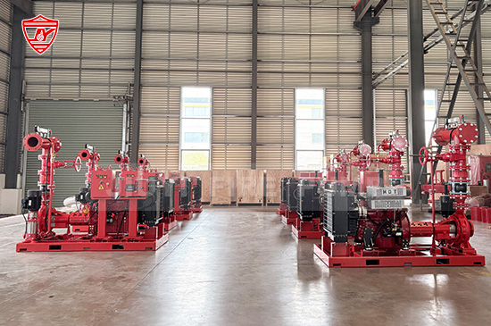
The fire pump is the primary component responsible for increasing water pressure and delivering the required flow rate to the fire protection system. When the water supply cannot provide sufficient pressure or flow, the fire pump helps meet the hydraulic requirements of the connected equipment.
Fire pumps are selected according to project-specific requirements, including flow rate, discharge pressure, water supply conditions, installation environment, and applicable fire protection standards.
Several types of fire pumps are commonly used in fire protection applications.
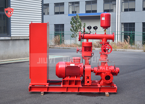
A horizontal split case fire pump is widely used in commercial buildings, industrial facilities, power plants, and large-scale fire protection projects. Its casing is divided horizontally, allowing convenient access to internal components for inspection and maintenance.
These pumps are suitable for applications requiring relatively high flow rates and stable performance. Their design also facilitates servicing and supports long-term operation when properly installed and maintained.
An end suction fire pump features a compact design, with water entering through the suction end and leaving through the discharge outlet. It is commonly used in commercial buildings, smaller industrial facilities, and fire protection systems where installation space is limited.
Its relatively simple construction makes it a practical option for projects that require dependable performance within a compact footprint.
A vertical turbine fire pump is designed for applications where the water source is located below the pump, such as underground tanks, reservoirs, wells, or other water sources with challenging suction conditions.
The pump uses a vertical shaft and multiple impellers or stages, depending on the design. It is particularly useful for industrial facilities, ports, large warehouses, and projects requiring water to be lifted from a deep source.
Depending on the project, fire pump systems may also incorporate other specialized configurations to meet particular hydraulic, spatial, or operational requirements.
The appropriate pump type should be determined through hydraulic calculations and an assessment of the installation conditions. Pump selection should not be based on flow rate alone; the required pressure, water source, motor or engine compatibility, and applicable approval requirements must also be considered.
The driver supplies the mechanical power needed to operate the fire pump. The two principal driver types are electric motors and diesel engines.
Electric fire pumps are driven by electric motors and are widely used in commercial buildings, manufacturing plants, residential developments, and industrial facilities.
An electric motor converts electrical energy into mechanical energy to drive the pump shaft. Motor selection must consider the pump's power requirements, voltage, frequency, starting characteristics, and installation conditions.
The electrical supply and associated equipment must be suitable for the intended fire protection application. Project designers should also evaluate the reliability of the power source and the requirements for emergency power, where applicable.
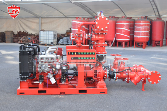
Diesel engine fire pumps are used when an independent mechanical drive is required or when the project calls for an alternative to an electrically driven main pump.
A diesel engine operates independently of the normal building electrical supply for its primary mechanical drive, although its starting system, controls, and auxiliary equipment still require appropriate electrical power.
A typical diesel-driven fire pump package includes the engine, fuel system, batteries, starting equipment, cooling arrangement, exhaust system, and related monitoring devices.
Fuel capacity, ventilation, exhaust routing, ambient temperature, maintenance access, and engine operating conditions must be considered during system design.
The choice between an electric motor and a diesel engine depends on the site's power reliability, project specifications, applicable codes, local regulations, and operational requirements.
Some facilities use both electric and diesel-driven fire pumps to provide additional redundancy or to meet specific design requirements. The final arrangement should be established by the fire protection designer based on the required system reliability and applicable standards.
The fire pump controller is responsible for controlling the starting and operation of the pump driver according to the system design and applicable requirements.
For an electric fire pump, the controller manages the motor-starting process and provides relevant operating indications and protective functions. For a diesel engine fire pump, the controller manages automatic starting, starting sequences, and engine-related monitoring functions.
A fire pump controller may include the following features:
Automatic and manual starting functions
Pressure-responsive starting inputs
Operating status indicators
Alarm and fault indications
Monitoring of relevant electrical or engine parameters
Interfaces for remote monitoring, where provided
The exact functions vary according to the driver type, controller design, and applicable standards.
It is important to distinguish a fire pump controller from an ordinary industrial motor control panel. Fire pump controllers are specifically designed for fire protection applications and must meet the requirements applicable to the installation.
Controller selection should consider the pump driver, available power supply, starting method, system configuration, and required approvals. Proper installation, commissioning, and testing are essential to verify that the controller responds correctly to the specified operating conditions.
A jockey pump, also known as a pressure maintenance pump, helps maintain pressure within the fire protection piping network during normal standby conditions.
Fire protection systems can experience small pressure variations caused by minor leakage, temperature changes, or other normal operating conditions. Without a jockey pump, these small pressure drops could cause the main fire pump to start unnecessarily.
The jockey pump is generally a smaller pump designed to compensate for minor pressure losses. It starts when system pressure falls below a predetermined setting and stops when the pressure returns to the specified level.
A typical jockey pump arrangement includes:
A small electric pump and motor
A pressure-responsive controller or control function
Pressure sensing equipment
Associated suction and discharge connections
Isolation valves and other required accessories
The jockey pump and main fire pump serve different purposes. The jockey pump maintains normal system pressure, while the main fire pump supplies the flow and pressure required during a fire protection demand.
Their pressure settings must be coordinated carefully to avoid unwanted starting and stopping. The jockey pump should not be used as a substitute for an appropriately sized main fire pump.
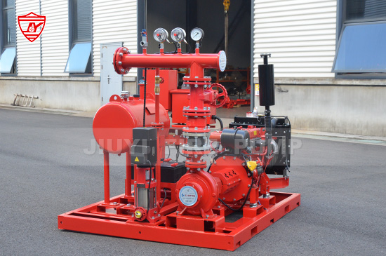
For many projects, a complete fire pump package includes an electric main pump, a diesel-driven standby pump, and a jockey pump. Other arrangements may be suitable depending on the project design and applicable requirements.
Piping connects the fire pump to the water source and distributes pressurized water to the fire protection network. Proper piping design is essential for achieving the required hydraulic performance and avoiding unnecessary losses.
Suction piping carries water from a tank, reservoir, municipal supply, or other approved source to the pump inlet.
Its design should account for pipe diameter, length, fittings, flow velocity, water source level, and pressure conditions. Poor suction piping design can contribute to excessive friction losses, unstable operation, and cavitation.
The suction arrangement must also be compatible with the selected pump type and installation conditions. Vertical turbine pumps, for example, have different source and installation requirements from conventional horizontal pumps.
Discharge piping carries pressurized water from the pump to the fire protection system.
Its design must accommodate the required flow rate and pressure while minimizing excessive hydraulic losses. Pipe materials, pressure ratings, supports, connections, and routing should comply with the applicable project specifications and standards.
Reducers, elbows, tees, flanges, expansion provisions where required, and other fittings connect the various parts of the system.
The arrangement of these fittings should be considered during hydraulic design because unnecessary restrictions and abrupt changes in direction can affect system performance.
Suction and discharge piping must be properly supported so that excessive loads are not transferred to the pump casing or its connections.
Valves control water movement, allow isolation for maintenance, and support inspection and testing. Their type, location, pressure rating, and approval status depend on the system design and applicable requirements.
Common valve types include the following.
A suction isolation valve allows the water supply connection to be isolated when permitted by the system design. Its arrangement must not compromise the availability of water to the fire pump.
A discharge isolation valve allows the pump discharge connection to be isolated for maintenance or other approved purposes. It must remain in the required operating position during normal service.
A check valve helps prevent reverse flow through the pump discharge connection. It supports proper system operation by limiting unwanted reverse movement of water when the pump stops.
A pressure relief valve may be required in certain configurations to manage excessive pressure under specified operating conditions. Its need and sizing depend on the pump characteristics, system design, and applicable requirements.
Where required, backflow prevention equipment protects the potable water supply from contamination caused by reverse flow.
Not every fire pump installation uses the same combination of valves. The required arrangement should be established according to the applicable fire protection standard, local regulations, and the approved system design.
Instrumentation provides information about the fire pump system's operating conditions. It helps installers, operators, and maintenance personnel verify that the system is functioning as intended.
Common instruments include suction pressure gauges, discharge pressure gauges, pressure switches, and other monitoring devices required by the design.
A suction pressure gauge indicates the pressure conditions at the pump inlet. A discharge pressure gauge indicates the pressure at the pump outlet. Comparing these readings can help operators evaluate the pump's operating condition, although pressure readings alone cannot confirm that the pump is delivering the required flow.
Pressure switches or pressure sensing devices may initiate automatic starting sequences when system pressure falls to the designated level.
Depending on the installation, additional instruments may monitor water temperature, engine temperature, oil pressure, battery condition, fuel level, or other parameters.
For diesel-driven fire pumps, appropriate engine monitoring is especially important because the engine must be ready to start and operate when required.
Instrumentation must be correctly selected, installed, calibrated where applicable, and maintained. Reliable readings support commissioning, troubleshooting, and periodic performance verification.
Fire pump performance must be verified through appropriate testing. Test headers and flow measurement equipment allow qualified personnel to evaluate the pump's hydraulic performance under controlled conditions.
A test header provides a connection for discharging water during testing. Depending on the design, it may accommodate multiple outlets and suitable hose connections.
Flow measurement equipment can measure the volume of water delivered by the pump. When combined with pressure readings and other relevant data, it helps establish whether the pump meets its specified performance requirements.
Testing may evaluate performance at different operating points, including rated flow and other points required by the applicable standard or project specification.
The exact testing arrangement depends on the pump installation, test equipment, water disposal arrangements, and local requirements.
A properly designed test arrangement should provide sufficient capacity for the required testing while maintaining safe operating conditions. Personnel must follow the applicable procedures and take appropriate precautions when handling pressurized water and operating machinery.
Diesel engine fire pump packages require additional components to support engine starting and continuous operation under the specified conditions.
The fuel system supplies diesel to the engine. Depending on the design, it includes a fuel tank, fuel lines, filtration equipment, and associated fittings.
Fuel capacity and installation arrangements must meet the project's requirements and applicable regulations. Fuel quality, storage conditions, and maintenance also affect engine reliability.
Starting batteries supply the electrical energy needed to crank the diesel engine. A typical installation includes the required battery arrangement, charging equipment, cables, and connections.
Battery condition must be monitored and maintained according to the manufacturer's recommendations and applicable requirements. Where multiple starting batteries or independent starting arrangements are required, the system must be configured accordingly.
Diesel engines generate heat during operation and therefore require a suitable cooling arrangement.
Depending on the engine design, cooling may involve a radiator, heat exchanger, or another approved arrangement. The cooling system must be suitable for the engine's rated operating conditions and the ambient environment.
The exhaust system safely directs engine exhaust away from the equipment room and occupied areas. Ventilation provides the air needed for combustion and helps manage heat generated by the engine and associated equipment.
These components are particularly important in enclosed pump rooms and containerized fire pump installations. Their design must account for airflow, exhaust backpressure, temperature, noise, and maintenance access.
The base frame supports the pump and its driver and helps maintain their alignment. Depending on the package configuration, it may also support associated equipment and piping connections.
A properly designed base frame provides structural stability and helps reduce the risk of alignment problems caused by installation or operating loads.
For coupled pump sets, pump and motor or engine alignment must be checked according to the manufacturer's instructions. Flexible couplings, where used, must be suitable for the application and installed correctly.
The foundation must support the equipment's weight and operating loads. Anchor bolts, grouting, vibration considerations, drainage, and access for inspection should be addressed during installation.
For packaged or containerized fire pump systems, the supporting structure may also integrate equipment mounting points, service access, ventilation provisions, and transport considerations.
Although the base frame is not responsible for generating hydraulic pressure, it plays an important role in the mechanical integrity and long-term reliability of the system.
The fire pump room or enclosure provides a suitable environment for the equipment and supports safe access for operation, inspection, and maintenance.
Its design should consider the type of pump, driver, local climate, available space, and applicable fire protection requirements.
Important considerations include:
Adequate access for maintenance and component replacement
Suitable ventilation and temperature control
Appropriate drainage and protection against flooding
Sufficient clearance around the equipment
Lighting and safe working conditions
Protection of electrical and control equipment
Suitable arrangements for fuel storage and exhaust systems where diesel engines are used
Containerized fire pump systems integrate the main equipment into a dedicated enclosure. Depending on the design, these packages may include the pump set, controllers, fuel system, ventilation, lighting, piping, and other supporting components.
A containerized solution can simplify transportation and on-site installation, particularly for industrial facilities, remote projects, ports, and locations where a conventional pump room is difficult to construct. However, the enclosure must still meet the environmental, structural, operational, and regulatory requirements of the project.
The performance of a fire pump system depends on the coordinated operation of its components rather than the performance of any single item.
Under normal standby conditions, the fire protection network remains pressurized. If minor pressure losses occur, the jockey pump may operate to restore pressure.
When a fire protection demand causes system pressure to fall to the designated starting threshold, the fire pump controller initiates the appropriate starting sequence. Depending on the system arrangement, an electric motor or diesel engine drives the main fire pump.
Water enters through the suction arrangement, passes through the pump, and is delivered at the required pressure and flow through the discharge piping. Valves direct and control water movement, while gauges and monitoring devices provide information about operating conditions.
During commissioning and periodic testing, qualified personnel verify the performance of the pump and associated equipment. Testing helps confirm that the system meets its specified requirements and identifies issues that may need correction.
The exact starting sequence, control logic, and operating arrangement depend on the system design and applicable standards. Fire pump systems should always be designed, installed, and commissioned by qualified professionals.
Selecting the right components requires a clear understanding of the project's hydraulic, electrical, mechanical, and operational requirements.
First, determine the required flow rate and pressure through appropriate hydraulic calculations. These values establish the basic performance requirements for the pump and influence the selection of the driver and associated equipment.
Second, evaluate the available water source. Water supply capacity, suction pressure, elevation differences, and installation conditions can influence the choice between horizontal split case, end suction, vertical turbine, and other pump configurations.
Third, select the driver and controller according to the required operating arrangement, available power, starting requirements, and applicable standards. Projects using diesel engines must also account for fuel storage, starting batteries, cooling, exhaust, and ventilation.
Fourth, specify the necessary piping, valves, instrumentation, and testing equipment. All components should be compatible with the expected operating pressure, flow rate, environment, and project requirements.
Finally, confirm the applicable approvals and standards. In projects requiring UL Listed or FM Approved equipment, the relevant certification scope and compatibility of the specified components should be verified. Compliance with NFPA 20 or other applicable requirements should be assessed according to the project jurisdiction and specifications.
A complete system should be evaluated as an integrated package. Selecting individually suitable components does not automatically guarantee that the assembled system will meet all performance and compliance requirements.
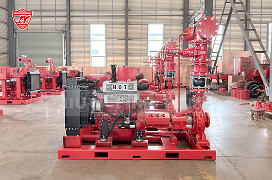
A fire pump system consists of multiple components that work together to provide dependable water supply for fire protection. The main components include the fire pump, electric motor or diesel engine, fire pump controller, jockey pump, suction and discharge piping, valves, instrumentation, testing equipment, and supporting mechanical and environmental systems.
Each component has a specific role, from generating the required water pressure to maintaining standby pressure, controlling operation, monitoring performance, and supporting maintenance.
For fire protection engineers, contractors, system integrators, and project owners, understanding these components helps improve equipment selection, system integration, installation quality, and long-term operational readiness.
As a fire pump manufacturer, BETTER Technology Group recognizes the importance of matching pump performance, driver configuration, control equipment, and supporting accessories to the requirements of each project. A well-engineered fire pump package should be designed around the actual application, verified through appropriate testing, and supported by proper installation and maintenance practices.
Whether the application involves commercial buildings, warehouses, ports, or petrochemical facilities, choosing a suitable fire pump system begins with understanding how its components work together to support reliable fire protection.