Ensuring that a fire pump performs according to its rated capacity is essential for the reliability and safety of any fire protection system. Fire pump performance testing—especially the flow rate verification—is a critical process required by international standards such as NFPA 20 and local fire authorities.
This article explains how to accurately verify fire pump flow rate performance, what equipment and methods are needed, and why regular testing is vital for system reliability and compliance.
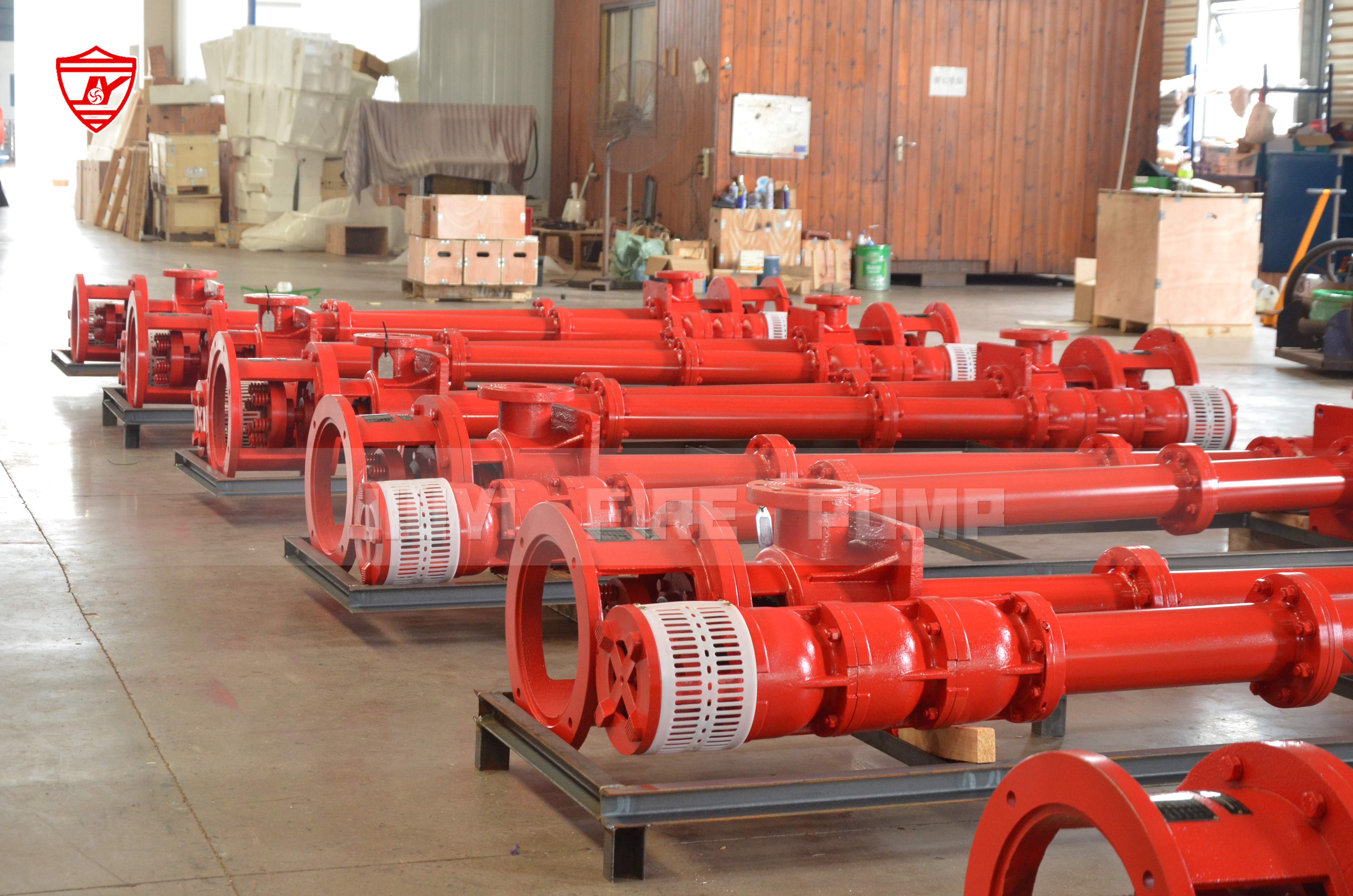
Fire pumps are designed to provide a specific flow rate and pressure at a designated duty point. If the pump fails to deliver the expected performance, the entire fire protection system may not supply sufficient water pressure during an emergency.
Verifying the pump’s flow rate performance ensures:
Compliance with NFPA 20 and UL/FM standards
Confirmation that the pump delivers its rated capacity
Early detection of performance degradation or mechanical issues
Reliable fire suppression during emergencies
Regular flow testing not only validates the pump’s original performance but also ensures it continues to operate within acceptable limits over time.
A fire pump flow test measures three main data points that define pump performance:
Churn (no-flow) condition – when the pump runs without any discharge.
Rated flow – when the pump operates at its nameplate flow rate and pressure.
150% of rated flow – when the pump delivers 150% of its rated flow, with pressure not dropping below 65% of the rated pressure.
The results are plotted on a pump performance curve to compare actual output against manufacturer data.
These tests are typically performed upon initial installation and annually thereafter as part of routine maintenance, in accordance with NFPA 25 (Standard for the Inspection, Testing, and Maintenance of Water-Based Fire Protection Systems).
To verify a fire pump’s flow rate accurately, the following equipment and instruments are used:
Flow meter or test header with calibrated pitot gauge
Pressure gauges on suction and discharge sides of the pump
Tachometer to measure pump speed
Thermometer to monitor water temperature (especially for diesel-driven pumps)
Static and residual pressure measuring devices
All equipment should be properly calibrated before use to ensure accurate readings.
Before starting, inspect the fire pump room and verify that all components are in proper working condition. Ensure:
Suction valves are fully open.
Relief valves and circulation lines are operational.
Test discharge lines are safely directed to drain or an open water source.
All personnel are briefed on the testing sequence.
Safety during testing is paramount, as sudden pressure changes or water discharge can pose hazards.
Document the following before the test begins:
Pump make, model, serial number, and rated capacity
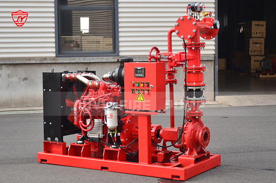
Type of driver (electric or diesel engine)
Suction and discharge pressures at rest
Water source type (tank, city main, reservoir, etc.)
These baseline data help identify any deviations during or after the test.
Start the fire pump with all discharge valves closed. This no-flow condition allows you to record:
Churn pressure (pressure at zero flow)
Pump speed (RPM)
Voltage and current (for electric pumps) or engine parameters (for diesel pumps)
The churn test verifies that the pump starts and builds up pressure properly without delivering water.
Next, open the discharge valves gradually until the rated flow is achieved. Measure and record:
Flow rate (using flow meter or pitot readings)
Suction and discharge pressures
Pump speed and driver load
At this stage, compare the discharge pressure to the manufacturer’s performance curve. It should match closely with the rated pressure specified for the rated flow.
Increase the discharge flow to 150% of the rated capacity while monitoring the pressure.
At this point:
The discharge pressure should not drop below 65% of the rated pressure.
Record all data points carefully.
This test ensures that the pump can handle demand beyond its rated flow without failure, confirming robustness and reserve capacity.
All test results are plotted on a performance curve showing:
Flow rate (x-axis)
Pressure (y-axis)
Three points—churn, rated flow, and 150% flow—are plotted to create a performance curve. The curve should closely match the manufacturer’s published data for that model.
If the test results show a significant deviation from the curve, it may indicate wear, impeller damage, obstruction in piping, or motor performance issues.
After testing, compare your results with the manufacturer’s certified performance curve:
Flow rate deviation within ±5% is generally acceptable.
Pressure deviation should not exceed ±5% of the rated pressure.
If the curve is consistently below the manufacturer’s data, further inspection or servicing may be required.
A decline in performance could result from factors such as:
Air leaks in suction lines
Blocked strainers or impellers
Worn bearings or seals
Incorrect pump speed
Electrical supply issues (for electric pumps)
Even experienced technicians can make errors that lead to inaccurate results. The most common issues include:
Using uncalibrated gauges or pitot tubes
Failing to fully open valves, restricting flow
Taking incorrect pitot readings from test headers
Ignoring water supply fluctuations during testing
Neglecting to record ambient conditions, such as water temperature
To ensure test accuracy, always calibrate instruments and follow a consistent test method aligned with NFPA guidelines.
NFPA 20 outlines the design and installation requirements for fire pumps, while NFPA 25 provides guidance for testing and maintenance.
According to NFPA 25:
Annual flow testing is mandatory for all fire pumps.
Acceptance testing must be performed upon installation to verify compliance with NFPA 20.
All results should be documented and retained for inspection and future comparison.
Compliance not only satisfies legal and insurance requirements but also ensures the fire protection system performs as designed in emergencies.
Verification doesn’t end after a successful test. Long-term reliability depends on ongoing maintenance and monitoring. Key recommendations include:
Monthly no-flow tests (churn tests) to ensure proper startup.
Quarterly or semiannual inspections of valves, gauges, and electrical connections.
Annual full flow tests following NFPA 25 standards.
Immediate corrective action if performance declines or abnormal vibration/noise occurs.
Regular preventive maintenance helps extend equipment life and ensures the pump remains ready for operation at any time.
While some facilities perform basic verification internally, third-party testing is often required for certification or compliance verification.
Professional fire pump test companies use calibrated instruments, certified technicians, and data logging systems to produce reliable results. Partnering with certified professionals ensures:
Accurate data collection
Compliance with international standards
Valid documentation for fire authority inspection
Verifying the flow rate performance of a fire pump is more than just a routine check—it’s a life-safety assurance process. Proper testing according to NFPA standards ensures that your fire pump system performs reliably when needed most.
By following a structured testing procedure, maintaining calibration accuracy, and keeping thorough records, facility managers and safety engineers can ensure long-term fire protection reliability.
For manufacturers, engineers, and building owners alike, a properly verified fire pump equals peace of mind, knowing that when the system is called upon, it will deliver its full rated performance to protect lives and property.