Efficient use of space in a fire pump room ensures safety, compliance, and streamlined operations. As a manufacturer of fire pumps, you understand that every square foot matters—be it for meeting code requirements, facilitating maintenance, or optimizing workflow. In this article, you’ll learn how to optimize fire pump room space by focusing on layout planning, equipment placement, safety access, ventilation, and future-proofing. Whether designing a new system or retrofitting an existing space, these practical strategies will help you deliver top performance while maintaining compact and code-compliant fire pump rooms.
Before any spatial optimization, familiarize yourself with fire codes such as NFPA 20, local building regulations, and insurance mandates.
Clearances and access: NFPA 20 requires minimum dimensions around equipment—typically a minimum of 36 inches of clearance in front of the pump for maintenance access, and 30 inches on the sides. Confirm local variations and document them.
Egress and door access: Design pump room access so doors swing appropriately and don’t intrude into working space. Ensure proper egress routes for safe exit.
Separation and fire protection: Certain jurisdictions may require rated walls or separation from other building areas. Account for added thickness in your spatial layout.
Ventilation and mechanical space: Codes often mandate adequate ventilation—typically 1 sq ft of unblocked opening per 1,000 BHP or similar—and room height limits to enable proper airflow.
By grounding design decisions in code compliance, you prevent costly revisions and ensure performance, safety, and reliability of fire pump operations.
Layout planning is the core of spatial optimization. Incorporate these design principles:
Group components logically: place driver (electric motor or diesel) adjacent to the pump, with piping and valves arranged for minimal bends and compact footprints.
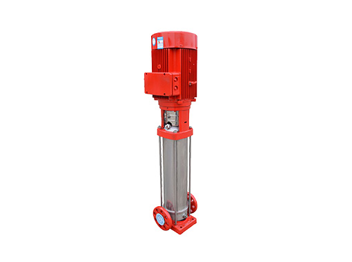
When ceiling height allows, consider vertical equipment mounting options:
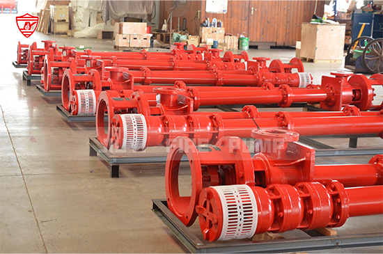
Vertical‐shaft pumps minimize horizontal space usage.
Wall-mounted control panels and instrument racks save floor space.
Design straight run piping where possible. Reducing elbows, flanges, and unnecessary bends conserves physical space, simplifies maintenance, and improves hydraulic efficiency.
Create overlapping zones — e.g., combine maintenance work clearance areas with walkway zones when scheduling; dual-use circulation space helps eliminate redundant walkway areas.
Use compact components—like efficient inline valves or low-profile controllers—and group gauges, valves, and alarms on panels rather than scattered along piping.
Sketch layout options early; use CAD or BIM to evaluate spacing and flow. Simulate clearances, maintenance pathways, and installation sequence to refine your design.
Optimization should never compromise serviceability:
Maintenance pathways: Maintain the required clearance in front of components; design for at least 30 inches of passageway, with wider spaces (≥36 inches) near major maintenance points.
Accessible equipment placement: Place heavy components (like pumps and motors) close to entry for easy hoisting, and align discharge or suction piping near accessible anchor points.
Service zones labeling: Designate clear service paths, align wall-mounted tools or parts cabinets on opposite walls to minimize congestion during maintenance.
Portable equipment space: If wheeled test pumps or tools are used, provide sufficient turning and staging zones without blocking egress routes.
A maintenance-friendly layout avoids costly downtime and improves overall safety by preventing cramped work conditions.
A compact room must still maintain proper environmental conditions:
Ventilation strategy: Install louvered intake and exhaust openings sized per pump HP (e.g., 1 sq ft per 1,000 BHP). Position them to maximize airflow without consuming wall space.
Low-profile ducts: Use low-profile or plenum ducts integrated into ceiling or top walls to preserve headroom.
Compact HVAC zones: Consider targeted spot cooling rather than full-room HVAC, or combine ventilation with HVAC pathways to serve dual purposes.
Climate considerations: In colder climates (like New Jersey), install frost-free louvers or electric heaters to prevent freezing, maintaining required space behind louvers for equipment clearance.
Smart environmental controls stabilize pump performance, avoid material degradation, and contribute to overall space efficiency.
Electrical and control systems play a pivotal role in room layout:
Wall-mounted control panels: Mount panels vertically to keep floor space open; use slimline panel designs.
Cable tray routing: Run cable trays above the access path, following ceiling lines to reduce intrusion into floor areas.
Shared utility pathways: Coordinate power, control, and fire-alarm wiring along shared conduits or trays to minimize ceiling clutter.
Monitoring hardware: Cluster gauges, sensors, and control instruments on compact consoles or manifolds placed next to the pump, reducing scattered instrument footprint.
Future-proof extra conduit: Plan capacity for additional conduit or panel expansion without compromising space later.
Optimizing control hardware placement ensures operational clarity and reduces clutter around critical systems.
Designing for today’s requirements while anticipating tomorrow’s upgrades:
Allow modular expansion: Include clear space or knock-out panels for adding a jockey pump, VFD, or automation equipment.
Scalable layout: Maintain adaptable zones that can absorb extra foot traffic, equipment, or piping without full redesign.
Pre-routed utilities: Provide stubbed conduits or blank manifolds for easy connection of future devices.
Access for equipment upgrades: Preserve pathways to bring in heavier or taller new components if needed.
Regular reviews and updates: Schedule layout re-evaluations during preventive maintenance intervals to optimize evolving operations.
A future-ready room reduces retrofit costs and improves lifecycle performance of your fire pump installations.
Situation: A mid-sized commercial building in New Jersey needed a new fire pump room in a confined mechanical area.
Challenges:
Limited floor space (approx. 150 sqft)
Tight ceiling height (9 feet)
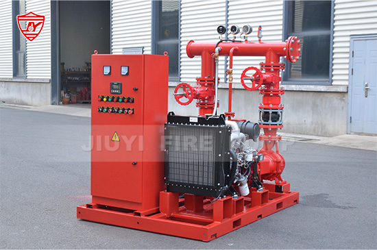
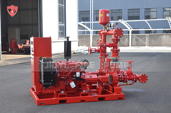
Requirement for diesel engine with associated ventilation and service access
Solution Approach:
Vertical pump selection allowed reducing horizontal footprint.
Wall-mounted control system, aligned near entry, cleared floor space.
Low-profile louvers and horizontally run ducting maintained headroom.
Straight-run suction/discharge piping, with minimal bends, conserved space.
Fold-out maintenance platforms for the diesel engine provided access when needed.
Integrated panelized gauge console kept instrumentation centralized and compact.
Stubbed conduit and service routing prepared for future addition of a jockey pump or remote monitoring.
Result: The design delivered full NFPA 20 compliance, excellent maintenance access, efficient ventilation, and foresight for future expansion—all within a tightly constrained space of under 150 sqft.
Optimizing fire pump room space is a balancing act between compact design and operational safety. You create efficient and reliable fire pump rooms by aligning layouts with code requirements, embracing modular and vertical strategies, maximizing maintenance access, fine-tuning ventilation and electrical routing, and anticipating future needs.
As a manufacturer, offering guidance or prefabricated room modules that integrate these principles can differentiate your services in the market. Prioritize thoughtful layouts and proactive planning to deliver dependable, space-wise fire pump rooms that meet client needs today—and tomorrow.