A UL fire pump set acceptance test is one of the most important procedures performed after installing a UL-listed fire pump system. Fire safety engineers, contractors, and building owners rely on this test to confirm that the pump performs exactly as required by UL standards and NFPA 20. Without passing this acceptance test, the fire pump cannot be considered fully operational or compliant for long-term fire protection.
For facilities such as high-rise buildings, industrial plants, warehouses, data centers, and critical infrastructure, the reliability of the fire pump set directly affects the safety of lives and property. That is why understanding the purpose, steps, requirements, and documentation of a UL fire pump acceptance test is essential for every fire protection professional.
This article explains what a UL fire pump set acceptance test is, what it includes, who performs it, the standards involved, and best practices to ensure your pump passes on the first attempt.
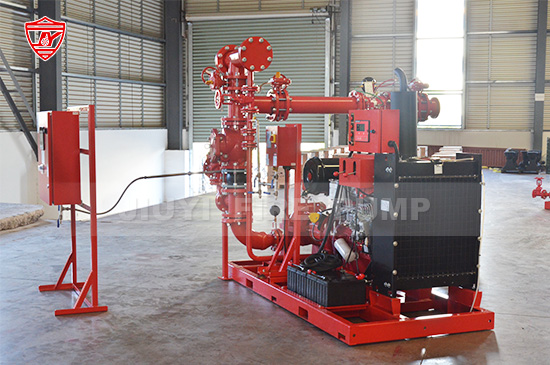
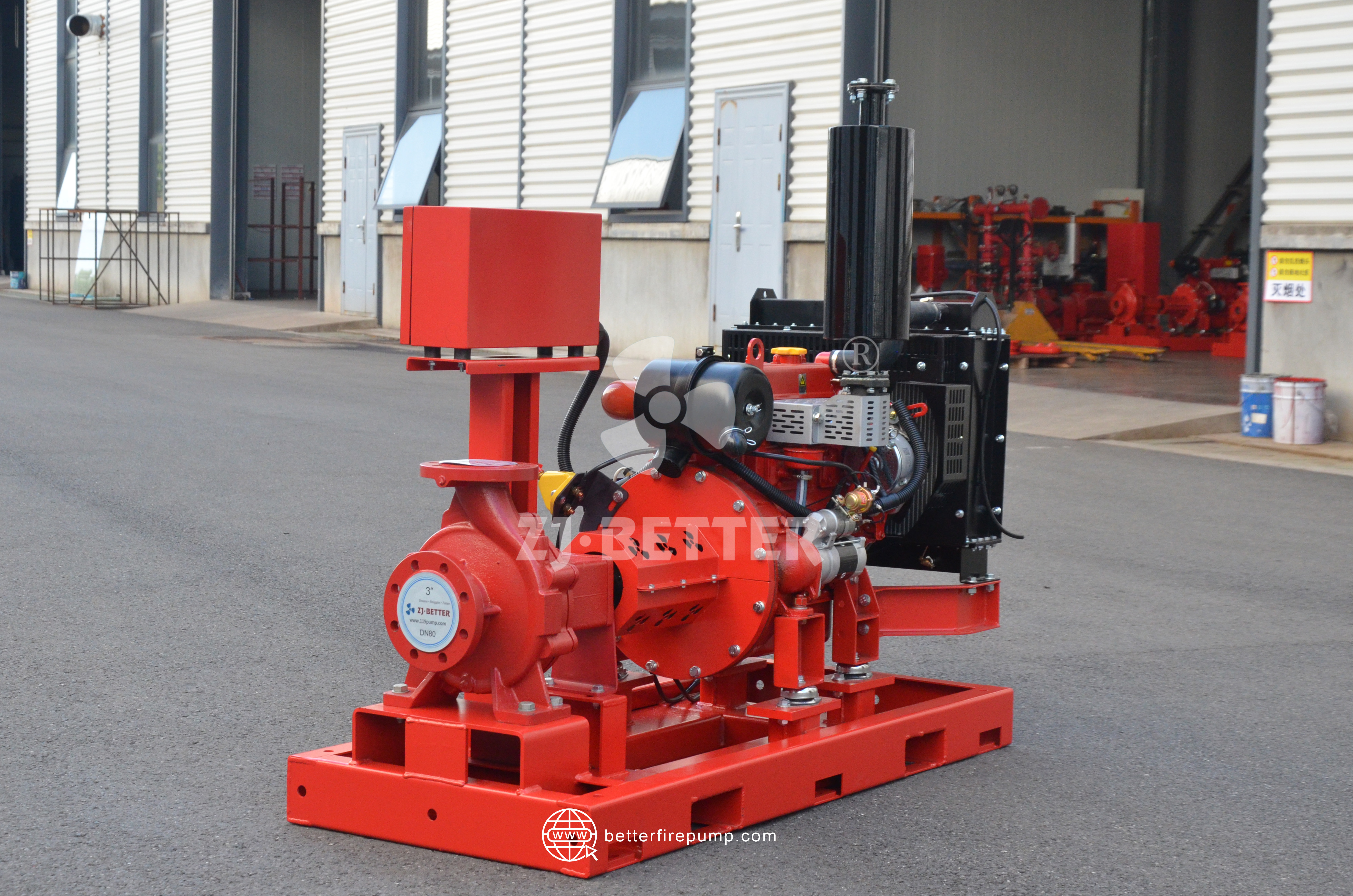
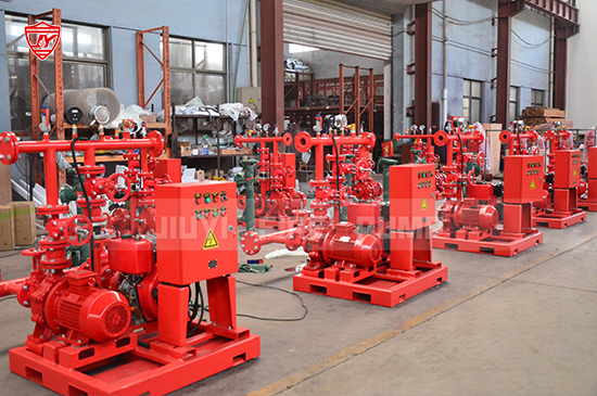
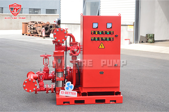
A UL fire pump set acceptance test is the official performance verification procedure carried out onsite to ensure that a newly installed UL-listed fire pump operates according to the manufacturer’s rated performance. It verifies that the entire fire pump package — including the pump, driver (diesel engine or electric motor), controller, valves, suction and discharge piping, and instrumentation — performs safely and reliably under actual load conditions.
This test confirms three major points:
The fire pump delivers the required flow and pressure at 100%, 150%, and churn (no flow).
The system complies with UL standards for fire pumps and associated components.
The installation meets NFPA 20 requirements, ensuring long-term operational safety.
Only after passing this acceptance test can the fire pump be officially commissioned and placed into service.
A UL fire pump is manufactured to meet strict safety and quality standards, but actual performance can only be confirmed through real onsite testing. The acceptance test serves several crucial purposes:
Pumps must match the manufacturer’s UL-listed rating in flow (GPM or L/min), pressure (PSI or bar), and speed (RPM). Deviations might indicate installation errors or equipment issues.
Improper suction piping, inadequate water supply, air entrapment, valve partially closed, or misalignment can reduce pump efficiency or cause failures.
Diesel engines, electric motors, and controllers must react correctly during automatic and manual starts, alarms, and fail-safe sequences.
Fire pumps are rarely used, so the acceptance test ensures that the system performs flawlessly when needed in emergencies.
NFPA 20, local fire authorities, and insurance agencies require documented acceptance testing before occupancy approval or commissioning.
The UL fire pump acceptance test is conducted in compliance with:
These standards specify design, construction, and test requirements for UL-listed fire pumps.
These cover performance, electrical safety, and reliability of pump drivers.
These ensure reliable starting sequences, alarms, and manual/automatic operation.
NFPA 20 provides the most detailed requirements for acceptance testing, water supply evaluation, piping layout, measurement equipment, and documentation.
Any UL fire pump set acceptance test must strictly follow these standards to ensure compliance.
The acceptance test is performed:
After installation of the fire pump set is fully completed
After electrical, mechanical, and piping work has passed inspections
After the pump room and water supply are ready
Before the system is officially handed over to the owner
Before the building obtains final occupancy approval
Contractors should never attempt the acceptance test until the system is stabilized and ready for full flow testing.
Typically, the test is conducted by a combination of:
Fire pump manufacturer or authorized representative
Fire protection contractor
Third-party testing agency
AHJ (Authority Having Jurisdiction) representatives
Owner’s fire safety team or consultant
The presence of all responsible parties ensures transparency, accurate documentation, and acceptance by local authorities.
A proper acceptance test requires:
Calibrated flow measuring devices (pitot gauges, flow meters, or test headers)
Pressure gauges on suction and discharge lines
Tachometer for driver speed
Thermometers for cooling water
Fuel measurement (for diesel engines)
Data recording sheets
All measuring instruments must be calibrated within the last 12 months to ensure accuracy.
Before running water, inspectors check:
Suction piping layout and water availability
Venting on the suction line
Proper pump and driver alignment
Valve positions
Controller wiring and settings
Diesel fuel supply, batteries, and cooling systems
Relief valve settings
Lubrication and mechanical condition
Any issue found here can prevent successful testing.
The pump runs with discharge valves closed.
This verifies:
Shutoff pressure
Controller operation
Vibration levels
Diesel engine behavior at no load
Temperature stability
Churn pressure must not exceed 140% of rated pressure, as required by UL and NFPA 20.
Discharge valves are opened to draw the pump’s exact rated flow.
Inspectors measure:
Suction pressure
Discharge pressure
Net pressure
Engine RPM or motor amperage
Controller performance
The pump must meet its rated pressure and flow as stated in the UL listing.
The pump is pushed beyond its normal operating point to 150% of rated flow.
This test determines:
Stability of pump performance
Adequacy of water supply
Capacity of the driver
Safety of running under overload
UL requires that the pump maintain at least 65% of its rated pressure at 150% of rated flow.
These include:
Simulating a pressure drop to confirm the pump starts without manual intervention.
Verifying automatic engine start when the primary battery fails.
Ensuring all alarms and supervisory signals report correctly to the fire alarm panel.
Switching between manual and automatic modes.
Even high-quality UL fire pumps may fail due to installation or operational issues. Common causes include:
Blocked strainers, low tank level, or piping restrictions can reduce suction pressure.
Using elbows too close to the pump or undersized pipes disrupts flow.
Air in the suction line reduces pump capacity and causes vibration.
Diesel engine RPM instability or electric motor overload issues.
Partially closed valves restrict flow during rated or overload tests.
Uncalibrated gauges lead to incorrect readings and failed reports.
Addressing these issues before testing ensures a smooth acceptance procedure.
The final acceptance report includes:
Complete performance data at churn, 100%, and 150% flow
Graphs (pump curve comparison, suction vs discharge pressure)
List of instruments used with calibration dates
Records of alarms and sequential tests
Driver and controller performance data
Installation notes and deviations
Certification from all parties present
This report is typically submitted to:
AHJ
Owner
Insurance provider
Fire pump manufacturer
It becomes the baseline for future annual pump tests required by NFPA 25.
Address piping, alignment, wiring, and hydraulic issues before testing begins.
Accurate readings prevent disputes and retesting.
Manufacturers understand the pump’s technical limits and can support troubleshooting.
Low water levels or restrictions lead to test failure.
They must understand operation, alarms, and maintenance.
Following these best practices saves time, reduces costs, and ensures your UL fire pump operates safely for years.

A UL fire pump set acceptance test is a critical procedure that confirms the installed pump meets UL and NFPA 20 performance requirements. It verifies system reliability, identifies installation issues, and ensures that the fire pump will perform when a real emergency occurs. For fire protection contractors, consultants, and building owners, understanding each step of this test helps avoid delays, ensure compliance, and guarantee long-term safety.