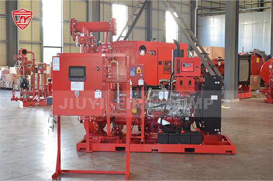
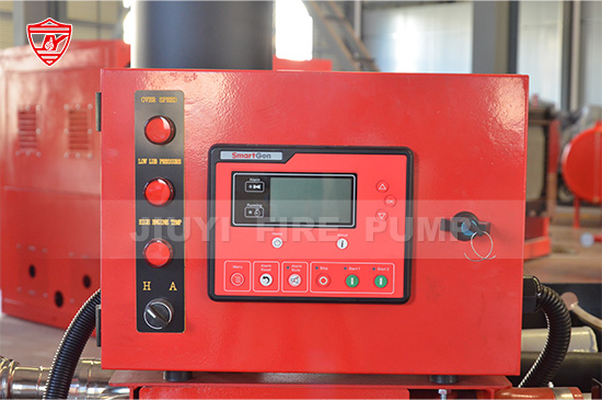
When discussing the reliability of any fire pump system, UL controller logic is one of the most important—but often least understood—components. A fire pump controller is the brain of the entire fire protection system. It ensures the fire pump starts when required, runs safely under all conditions, communicates faults, and complies with international safety standards.
For projects requiring UL-Listed equipment, understanding UL controller logic is essential. It affects system reliability, commissioning success, long-term performance, and even acceptance during third-party inspections. This article offers a complete and practical explanation of how UL controller logic works, what makes it different from non-UL systems, and why it matters for fire safety professionals, consultants, contractors, and building owners.

UL controller logic refers to the specific electrical design, start/stop sequence, protection features, safety interlocks, and monitoring functions required by UL standards—primarily UL 218, UL 508, and the performance criteria cross-referenced with NFPA 20.
A UL-Listed fire pump controller must pass rigorous testing by Underwriters Laboratories. The controller must demonstrate the ability to:
Start the fire pump reliably under any fire demand
Run continuously without tripping on overload
Operate even under adverse electrical conditions
Provide accurate alarms and fault signals
Protect the pump without compromising emergency operation
In simple terms, UL controller logic ensures the pump will always start during a fire, and it will never stop unless an operator intentionally shuts it down.
Fire protection is a life-safety system. Unlike industrial pumps that can shut down for safety or maintenance, a fire pump must run even under damage, fluctuation, or severe conditions.
UL controller logic helps achieve this by ensuring:
Fail-safe startup even with power irregularities
Protection without interference to emergency operation
Accurate signals to building management systems
Standardized functionality across manufacturers
High reliability during fire emergencies
Buildings such as high-rise towers, airports, industrial plants, oil & gas facilities, and commercial complexes increasingly require UL-Listed fire pump systems. Controller logic is one of the main reasons UL systems are accepted globally.
UL controllers use multiple independent start methods to ensure the fire pump starts under any condition. In most UL electric fire pump controllers, the sequence includes:
The most common method. When system pressure falls below a preset point, the controller receives a signal to start the pump in seconds.
UL requires pressure switches to be supervised and designed so that failure leads to a start signal, not a system failure.
An operator can initiate pump operation at the local controller panel.
However, UL logic prevents an operator from blocking automatic starts.
UL controllers accept start commands from:
Fire alarm panels
Building management systems
Remote push stations
These are start-only circuits; remote stop is never allowed.
If the jockey pump runs continuously or cannot restore pressure, the controller recognizes abnormal system pressure and initiates pump start.
If electrical power returns after an outage, UL logic requires the motor to automatically re-start without operator intervention.
The goal is simple: the pump must start no matter what.
UL logic is deliberately designed to make stopping the pump difficult. The system must not stop unintentionally during a fire.
UL controllers only allow two types of pump shutdown:
An operator must open the panel door and press the stop button. This ensures the pump does not stop accidentally.
This is usually a protected stop button located near the controller, not on a remote system.
No automatic stop based on pressure recovery
No automatic stop based on time delay
No remote stop from BMS or fire alarm system
No stop signal from sensors
Why? Because automatic stop logic could accidentally shut down the pump during an active fire event.
UL logic requires duplication of critical elements like:
Start circuits
Pressure switches
Power pathways
Redundancy ensures no single failure prevents pump start.
Unlike standard motor systems, UL pump controllers do not trip on overload during fire emergencies.
They can alarm, but they will not disconnect the motor.
UL requires the controller to attempt startup even during high mechanical resistance.
This protects against failures such as:
Debris in the impeller
Seized bearings
Pressure‐locked pipelines
The controller must still energize the motor.
UL logic includes alarms and indicators for electrical faults but does not stop the pump.
Only manual shutdown is allowed.
UL controllers, combined with NFPA requirements, enforce:
No premature stop
Continuous running during fire mode
Manual investigation before shutdown
This avoids multiple starts that may damage systems in unstable pressure environments.
Diesel engine controllers have additional complexity. Key UL logic functions include:
The controller must manage two independent battery banks.
If one fails, the other automatically takes over.
UL logic requires several start attempts, each with a programmed crank/rest cycle.
The engine must start even under weak battery conditions.
Fuel delivery must start and remain open during pump operation, with fail-safe design.
This is the only condition where UL allows automatic shutdown, due to catastrophic mechanical risk.
UL diesel controllers alarm but do not shut down for:
High engine temperature
Low oil pressure
The system must continue running until manually stopped.
UL controller logic incorporates multiple interlocks to prevent unsafe operation while ensuring pump availability:
The start and stop functions are accessible, but live components remain protected.
Prevents simultaneous contradictory signals (e.g., start/stop conflicts).
Circuit failure results in automatic pump start—not a system failure.
Even if sensors fail, the operator can always start the pump.
For electric pumps using diesel generators, UL logic ensures:
Transfer to generator within a specified time
Booster start logic if voltage is too low
Automatic return when normal power is restored
These interlocks are essential for mission-critical buildings.
A UL fire pump controller includes and supervises:
Main contactors or soft starters
Run/unloaded logic (if allowed by UL type)
Frequency monitoring circuits
Motor protective devices (alarm only)
Battery chargers (diesel units)
Fuel solenoids
Pressure sensors
Remote start terminals
Recorder or event logger
Alarms (pump running, phase failure, system trouble)
Every component follows UL’s fail-safe logic requirements.
| Feature | UL Controller Logic | Non-UL Controller Logic |
|---|---|---|
| Startup reliability | Redundant and guaranteed | Depends on design |
| Automatic stop | Not allowed | Common in many systems |
| Electrical protections | Alarm only | Often shutdown |
| Test requirements | Extremely strict | Less standardized |
| Compliance | UL + NFPA 20 | May vary by region |
| Safety interlocks | Mandatory | Not always included |
In real project conditions, the difference translates into:
Higher reliability
Higher cost initially
Far fewer failure incidents
Easier acceptance during audits
Longer controller lifespan
Understanding controller logic helps engineers and building owners:
Select the right controller type
Diagnose starting or pressure issues
Plan system commissioning
Ensure NFPA 20 compliance
Communicate effectively with inspectors
Improve long-term fire pump performance
As fire safety systems become more standardized globally, knowledge of UL controller logic is increasingly essential.

UL controller logic is at the core of a reliable, compliant, and high-performance fire pump system. It guarantees that the pump will always start during a fire, continue to run under extreme conditions, and provide clear and accurate system alarms.