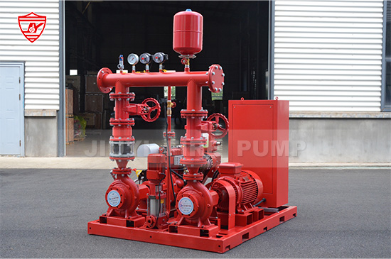
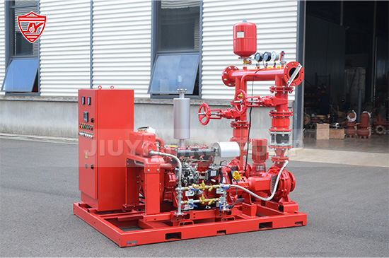
Fire pumps play a critical role in fire protection systems, ensuring water is delivered at the required pressure and flow to control or extinguish fires effectively. Among the essential concepts in fire pump engineering is the fire pump duty point, a term that every fire protection engineer, designer, or facility manager should understand. This article explains what a fire pump duty point is, why it matters, and how to calculate it to ensure optimal performance.

The duty point of a fire pump is the operating condition at which the pump performs most efficiently and meets the system’s required flow and pressure. In simpler terms, it is the intersection point between the pump’s performance curve and the system curve.
Pump Performance Curve: This curve, provided by the pump manufacturer, shows the relationship between the flow rate (usually measured in gallons per minute or liters per second) and the pressure (or head) the pump can deliver.
System Curve: This curve represents the pressure required by the fire protection system at different flow rates. It accounts for factors such as pipe friction, elevation changes, and equipment losses.
The duty point ensures that the fire pump delivers the necessary water flow at the correct pressure to the fire sprinkler system or standpipe system. Operating outside the duty point can lead to insufficient water supply, excessive wear, or even pump failure.
Accurately determining the fire pump duty point is crucial for several reasons:
Compliance with Standards: Fire pump installation and performance are regulated by standards such as NFPA 20. The duty point ensures the pump meets these standards.
System Reliability: A correctly calculated duty point ensures that the fire pump can supply water at the required pressure during a fire event.
Energy Efficiency: Operating at or near the duty point reduces energy consumption and wear, prolonging the pump’s service life.
Safety: Underestimating the required duty point can result in insufficient water pressure, compromising fire protection. Overestimating it can lead to unnecessary strain and potential system damage.
Understanding the duty point is not only essential for engineers and designers but also for maintenance personnel who monitor pump performance and make operational adjustments.
Several factors influence where the duty point falls on the performance curve:
Required Flow Rate: Determined by the design of the fire protection system, including sprinklers, hose reels, and hydrants.
Required Pressure/Head: The pressure needed to overcome system losses and ensure adequate water delivery at the most remote point in the system.
Pump Type: End suction, vertical turbine, and split case fire pumps have different performance characteristics.
System Resistance: Friction losses in pipes, valves, fittings, and elevation changes affect the system curve.
Safety Margins: NFPA standards require certain safety margins, such as a 10% pressure increase, to account for uncertainties and system aging.
Calculating the duty point involves matching the pump performance curve with the system curve. The following steps outline a standard approach:
Before calculating the duty point, define the flow rate and pressure required by the fire protection system. These are usually based on NFPA guidelines and the system design:
Identify the required flow rate in gallons per minute (GPM) or liters per second (L/s).
Determine the required pressure at the most hydraulically remote point of the system.
System losses are the resistance that the pump must overcome to deliver water effectively. This includes:
Friction Losses in Piping: Calculated using the Darcy-Weisbach or Hazen-Williams formulas based on pipe diameter, length, and material.
Fittings and Valves Losses: Additional pressure losses caused by elbows, tees, valves, and other fittings.
Elevation Head: The vertical height difference between the pump and the highest point of the system.
The total system head at the required flow is the sum of all these losses plus the pressure needed at the most remote sprinkler or outlet.
Once the system losses are calculated for varying flow rates, plot the system curve. This curve rises with increasing flow because friction losses increase with higher flow rates. The vertical axis represents pressure or head, and the horizontal axis represents flow rate.
The pump performance curve is provided by the pump manufacturer. It shows the relationship between the pump’s flow rate and the head it can produce at a given speed. Different pumps have different curves, and curves may also change depending on impeller diameter or motor speed.
The duty point is where the pump curve intersects the system curve. At this point:
The pump can deliver the required flow rate.
The pressure developed by the pump meets the system’s requirements.
For example, if a fire system requires 500 GPM at 150 PSI, the pump’s curve should indicate that it can produce 150 PSI at a flow of 500 GPM. This is the pump’s duty point.
After identifying the duty point, verify that it lies within the recommended operating range of the pump. Operating outside this range can reduce efficiency and cause mechanical issues.
Minimum Flow: Ensures adequate cooling and prevents cavitation.
Maximum Flow: Prevents excessive vibration, overheating, and seal damage.
If the calculated duty point is outside the pump’s optimal range, adjustments may be necessary:
Select a different pump or impeller size.
Modify the system design to reduce friction losses or pressure requirements.
Consider installing a variable frequency drive (VFD) if flow variability is needed.
Even experienced engineers can make mistakes when determining the fire pump duty point. Some common errors include:
Ignoring System Changes: Changes such as additional sprinklers, pipe extensions, or valve replacements can affect system losses.
Incorrect Friction Loss Calculations: Using wrong coefficients or neglecting fittings and valves can skew results.
Overlooking Safety Margins: NFPA standards require specific margins to ensure reliability, which are sometimes omitted in calculations.
Assuming Pump Curves are Absolute: Real-world pump performance may vary slightly from manufacturer data due to wear, installation conditions, and pump age.
Regular Testing: Conduct regular fire pump performance tests to verify the duty point aligns with system requirements.
Documentation: Maintain accurate records of pump curves, system curves, and test results.
Professional Consultation: In complex systems, consult with fire protection engineers to ensure proper duty point calculation.
Consider Future Expansion: Design the pump system with potential future flow and pressure requirements in mind.

The fire pump duty point is a fundamental concept in fire protection engineering. It ensures that the fire pump delivers water at the correct flow and pressure, complying with standards and safeguarding lives and property. By understanding the components that affect the duty point and following systematic calculation steps, engineers and facility managers can optimize fire pump performance, enhance system reliability, and ensure safety in emergency situations.
Whether designing a new fire protection system or maintaining an existing one, accurately calculating and monitoring the fire pump duty point is critical. It is the intersection where the fire pump and the system work in harmony, providing the assurance that when a fire occurs, the system will perform as intended.