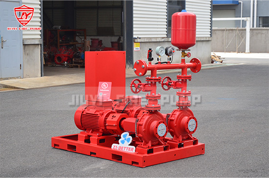
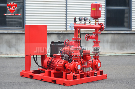
In fire protection systems, fire pumps play a critical role in delivering water pressure when needed most. But they don’t simply switch on and begin pumping instantly — there's a precise sequence of operation that governs how they start, run, and shut down. For fire safety professionals, understanding that sequence is essential for ensuring compliance, reliability, and safe operation.
This article walks you through every step of the fire pump sequence of operation, referencing key NFPA requirements and best practices. Along the way, you'll learn why each step matters and how you can confirm your fire pump system is built and maintained to the highest standards.

The fire pump sequence begins when a demand signal is detected — typically when a fire sprinkler or standpipe opens, causing system pressure to drop below a set point. This low-pressure condition is sensed by the fire pump controller.
Common triggers include:
Activation of a sprinkler head.
Manual initiation from a fire protection valve.
Loss of pressure in the fire protection piping network.
Upon detecting low pressure, the fire pump controller initiates a timing delay—often 10 seconds (per NFPA 20 and NFPA 25 guidance, subject to what the installed controller is configured for). This delay serves to:
Prevent false starts caused by transient pressure fluctuations.
Give jockey pumps a chance to correct minor pressure drops without engaging the fire pump.
If pressure remains low after the delay, the controller proceeds to start the fire pump.
Depending on pump type:
Electric Fire Pump: The controller connects mains power to the motor, ramping up to full speed.
Diesel Fire Pump: The electric start engages the diesel engine, which cranks and starts, then the diesel controller tunes engine speed to reach nominal RPM before connecting the pump.
At startup, the controller signals “Pump Running.” Simultaneously, it triggers audible and visible alarms, alerting operators and monitoring systems.
Once the pump is operational, the system verifies it is delivering adequate flow and pressure, ensuring the pump has properly engaged and is doing its job.
Important checks include:
Monitoring pressure gauges (both suction and discharge).
Ensuring discharge exceeds the system’s design pressure demand.
Confirming no cavitation or abnormal vibration, which can indicate mechanical or hydraulic issues.
If flow/pressure are inadequate, the controller may trigger a fault alarm or attempt restart procedures as configured.
For electric pumps, especially in critical installations, fire pump controllers often include an alternate power source (e.g. diesel generator or backup mains). If primary power fails during operation:
The controller transfers load to the standby power source within the allowed transfer time (often 10 seconds).
The pump remains engaged, keeping fire protection intact.
Controllers are tested periodically to ensure that automatic transfer works reliably.
While the fire pump runs:
Pressure is maintained to meet hydraulic demand.
Pump status (running, standby, fault) is recorded and transmitted to building management or fire alarm systems.
Event logging and alarm records capture every activity for compliance and post-event analysis.
Routine tests per NFPA 25 ensure readiness — e.g., weekly churn tests and annual full-flow tests.
Once the sprinkler heads close or the demand ceases:
The system pressure gradually returns to normal.
When pressure rises above the cutoff threshold, the controller waits for a short settling delay (5–10 seconds) to avoid nuisance cycling.
If pressure remains stable above the setpoint after the delay:
Electric pump: Disconnector stops motor; pump shuts down automatically.
Diesel pump: Controller activates cool down for a short period (allowing engine to coast), then shuts off fuel supply and stops the engine.
The controller resets to standby mode, ready for the next demand.
With the fire pump safe and idle:
The system resets "Pump Running" alarms.
Faults or warnings must be cleared manually after confirming correct operation.
Any supervisory signals to a central monitoring station (e.g. via fire alarm panel or building automation) are reset once the condition has returned to normal.
Finally, documentation and maintenance steps are key:
Logging the event helps with code compliance and system history.
After any real activation, conduct an inspection to confirm proper operation, evaluate wear, and reset system readiness.
If a fault occurred, schedule repair or testing to fix root causes (e.g., worn parts, faulty sensors, improper delays).
| Step | Description |
|---|---|
| 1 | Demand detected (pressure drop / valve opening) |
| 2 | Controller delay to filter transient drops |
| 3 | Pump start (electric or diesel) |
| 4 | Flow/pressure verification after startup |
| 5 | Alternate power transfer (if electric pump) |
| 6 | Ongoing operation with monitoring |
| 7 | Demand cessation & pressure recovery |
| 8 | Pump shutdown & transition to standby |
| 9 | Alarm reset and notification clearing |
| 10 | Logging and maintenance follow-up |
Regulatory compliance: NFPA standards mandate proper start/stop logic, delays, and alarm handling for safe and reliable fire protection.
Avoiding false activations: Delays and verification steps prevent pump cycling for minor fluctuations.
Operational reliability: Alternate power capability and monitoring ensure uninterrupted protection during emergencies.
Maintenance insights: Logging sequences and alarms helps find potential issues before a real incident.
Calibrate delay periods (e.g. 10s start delay, 5–10s stop delay) based on system dynamics—not just default settings.
Test alternate power transfers routinely to ensure seamless switchover under load.
Use digital controllers capable of event logging and remote annunciation, supporting preventive maintenance.
Train staff on alarm types (e.g., "pump running" vs. "fault" indicators) and reset procedures.
Document all tests and real activations, to satisfy NFPA 25 yearly inspection requirements and internal QA tracking.

Understanding the detailed fire pump sequence of operation is more than academic—it’s the cornerstone of reliable fire protection. From demand detection to power transfer, from startup verification to post-event maintenance, every step ensures that when fire strikes, your system responds swiftly, safely, and effectively.
By aligning your equipment and procedures with this sequence—and the NFPA guidelines behind it—you elevate both performance and compliance. Should you need equipment recommendations, training materials, or controller programming support, your fire pump manufacturer is here to help.