Designing an efficient and compliant fire pump suction system is a critical step in ensuring that your fire protection system operates reliably during an emergency. Improper suction design can lead to pump cavitation, reduced performance, or even complete system failure — outcomes that no facility can afford when lives and property are at stake.
In this article, we’ll explore the essential elements of fire pump suction design, including layout considerations, hydraulic principles, pipe sizing, and best practices according to NFPA 20 and other global standards.
The suction side of a fire pump is the pipeline that supplies water from the source (such as a tank, reservoir, or public main) into the fire pump. Its purpose is to ensure an adequate and consistent flow of water under the correct pressure conditions.
If the suction design is poor — for instance, if the pipe is too small, has too many bends, or allows air pockets — the pump may not receive enough water. This can cause low pressure, unstable performance, or even cavitation, where vapor bubbles collapse and damage the impeller.
A properly designed suction system ensures:
Uninterrupted water supply to the pump
Sufficient pressure and flow rate
Stable operation during all demand conditions
Compliance with standards such as NFPA 20
Depending on the water source and installation environment, fire pumps can use several suction arrangements:
When the municipal water supply is reliable and maintains adequate pressure, the fire pump may draw directly from it. In this setup, it’s vital to ensure the city main can sustain fire demand without excessive pressure drop.
Many systems use a fire water storage tank as the suction source. This provides a guaranteed volume of water independent of city mains. The tank must be designed with appropriate fittings, strainers, and minimum water levels as specified by NFPA 22.
In some industrial or remote installations, the water source may be a pond or reservoir. Vertical turbine pumps are typically used here, as they are designed to draw water from below-grade sources with long suction lifts.
Each suction type requires different design considerations for pipe routing, velocity limits, and net positive suction head (NPSH).
To ensure efficient water delivery to the fire pump, several design factors must be carefully controlled:
The suction pipe must be large enough to minimize friction loss and prevent excessive velocity. According to NFPA 20:
Suction pipe velocity should not exceed 15 ft/s (4.6 m/s).
In most cases, it’s better to keep velocity below 10 ft/s (3 m/s) to reduce turbulence.
Undersized pipes can cause pressure drops and affect the pump’s NPSH available (NPSHa).
NFPA 20 recommends that the suction pipe be at least 10 pipe diameters of straight length immediately before entering the pump. This minimizes turbulence and ensures a uniform flow into the impeller eye.
When reducing pipe size at the suction inlet, always use eccentric reducers flat on top (FOT). This prevents air pockets from forming at the top of the suction line, which could cause cavitation.
Suction pipes should be laid out to prevent air accumulation. Sloping the suction pipe slightly upward toward the pump helps release any trapped air.
Strainers may be used to prevent debris from entering the pump, especially when drawing from tanks or open sources. However, they must be designed with minimal pressure loss and easy maintenance access.
NPSH (Net Positive Suction Head) measures the absolute pressure at the pump suction compared to the vapor pressure of the liquid. If the NPSH available (NPSHa) is less than the NPSH required (NPSHr) by the pump, cavitation will occur.
NPSHa = Atmospheric Pressure + Static Head – Friction Loss – Vapor Pressure
To prevent cavitation, always ensure:
NPSHa ≥ NPSHr + Safety Margin (typically 1 meter or 3 feet minimum).
Keep suction lift to a minimum.
Use large, smooth-radius bends instead of sharp elbows.
Minimize fittings and valves on the suction side.
Ensure the water temperature is within design limits (higher temperatures reduce NPSHa).
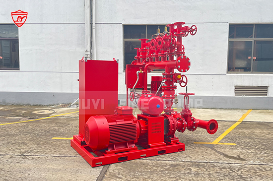
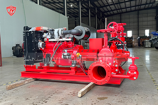
Horizontal split case fire pumps are the most commonly used type in building and industrial fire systems. Their suction layout should follow these principles:
The suction pipe should approach the pump horizontally and straight, with no elbows immediately before the suction flange.
Install eccentric reducer (flat on top) directly at the pump suction.
Provide isolation valves such as OS&Y gate valves, but avoid installing them too close to the suction flange.
Ensure proper clearance for maintenance and alignment.
Avoid high points or trapped air zones in the suction line.
When using dual fire pumps, each pump must have its own dedicated suction pipe from the header to avoid flow interference.
Vertical turbine fire pumps are designed for use with open water sources or tanks where the water level is below the pump. Unlike horizontal pumps, they do not require suction piping — the column pipe and bowl assembly serve that purpose.
Design considerations include:
The pump bowl must always remain submerged at the minimum water level.
Adequate clearance between the suction bell and tank bottom (typically ≥ 0.5 times the suction bell diameter).
Proper sizing of the discharge head and column pipe to minimize head loss.
The suction strainer must be corrosion-resistant and easily removable.
Even minor suction design errors can lead to costly performance issues. Some of the most frequent mistakes include:
Installing an elbow right before the pump inlet — causes uneven velocity distribution and cavitation.
Using concentric reducers instead of eccentric (flat on top) — can trap air at the top of the pipe.
Insufficient pipe diameter — leads to high friction losses and reduced NPSHa.
Improper venting or sloping — allows air pockets to form.
Connecting multiple pumps to a common suction header without proper spacing or flow balance.
Excessive suction lift — reduces NPSHa, especially in vertical lift installations.
Avoiding these pitfalls during design ensures longer pump life, stable performance, and compliance with fire safety standards.
NFPA 20, “Standard for the Installation of Stationary Pumps for Fire Protection,” is the primary reference for fire pump suction design. It defines requirements for suction piping, fittings, valves, strainers, and acceptable velocities.
Additional regional standards that complement NFPA 20 include:
UL 448: Requirements for centrifugal fire pumps.
FM Global Property Loss Prevention Data Sheets: Guidance on pump room and suction configuration.
Local fire codes or water authority regulations that govern installation details.
Following these standards ensures your system is not only efficient but also approved for insurance and inspection compliance.
To summarize, here are the top design practices for reliable suction performance:
Keep suction piping as short and straight as possible.
Size suction lines generously to limit velocity below 15 ft/s.
Use eccentric reducers flat on top.
Maintain a straight run of 10 pipe diameters before the pump.
Ensure proper venting and avoid air pockets.
Verify NPSHa exceeds NPSHr by a safe margin.
Follow NFPA 20, UL, and local standards for layout and materials.
Test and inspect suction performance during commissioning.
A well-designed fire pump suction system is the foundation of any reliable fire protection system. It ensures that your fire pump operates at full efficiency when it matters most — during an emergency.