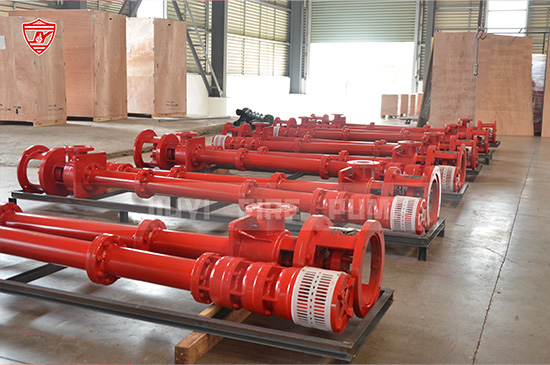
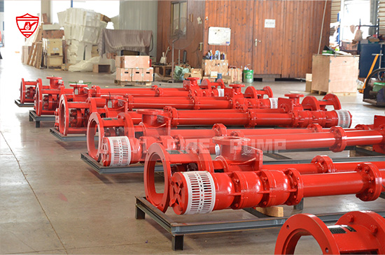
Vertical turbine pumps are central to fire protection systems, especially when water must be drawn from deep reservoirs, wells, or sumps. The crucial component that lifts—and maintains—the water flow is the impeller, working with other key parts to deliver adequate pressure and volume. This article explores how these components function, design best practices, and considerations for fire safety applications.

Vertical turbine pumps are designed for vertical installation, often in wells or underground sumps. Core components include:
Impellers: The rotating components that impart energy to the water.
Bowl assembly (stages): Guides water from one impeller to the next.
Pump shaft and shaft coupling: Transmits engine or motor torque down the turbine column.
Column pipe: Provides pathway and structural alignment for water and shaft.
Suction bowl / intake: Where water enters the pump assembly.
In fire pump applications, precision in impeller design and the bowl assembly configuration determines whether water can be lifted reliably, especially under high-pressure demands. Secondary features—like thrust bearings and wear rings—ensure mechanical stability and efficient flow.
At the heart of the action is the impeller—a radial-blade or mixed-flow device that converts mechanical force into fluid motion. Here’s how:
Rotation & Velocity: As the impeller spins, blades throw water outward (centrifugal force).
Energy Transfer: Kinetic energy from spinning is transformed into pressure.
Stage-by-Stage Lift: In multistage pumps, each impeller (in its bowl) adds head, incrementally lifting water higher.
Pressure Rise: The staged design boosts pressure without overloading a single impeller, ensuring smooth, reliable lift.
Guiding Pathways: Stationary bowl diffusers or diffuser vanes between stages guide water toward the next stage.
These actions combine to ensure consistent flow—with high head and pressure—far exceeding what single-stage or centrifugal pumps often deliver in deep-draw scenarios.
Let’s break down each vital part that works in harmony to lift water:
Type: Closed, semi-open, or open—depending on debris handling and efficiency needs.
Material: Stainless steel or bronze for corrosion resistance and fire-rated reliability.
Balance & Precision: Strict tolerances to minimize vibration and wear, crucial in fire safety systems.
Act as intermediate chambers between impellers.
Include diffuser vanes that convert flow velocity into pressure.
Critical to maintain laminar, efficient flow and minimize head loss.
The shaft transmits rotational energy from above-ground motors or diesel engines down through the column.
Flexible couplings accommodate slight misalignments and reduce stress, enhancing service life.
Houses the shaft and channels water upward along each stage.
Must resist internal pressure and external environmental factors (e.g., groundwater corrosion).
Thrust bearings: Absorb axial load from pressurized water flow, protect the motor and mechanical seals.
Wear rings: Maintain close clearances between impellers and bowls to minimize recirculation and efficiency loss.
Include screen, foot valve, or suction bell to ensure clean water intake.
Proper sizing prevents cavitation—a major enemy of reliable pump operation.
Fire safety applications impose unique demands:
Rapid Start-Up: Impellers must handle high acceleration stresses; rotor dynamics and hydraulic balance are critical.
High Duty & Reliability: Pumps operate in emergency conditions—impeller erosion, shaft alignment, and bowl wear demand rugged designs and maintainability.
Temperature Extremes: In cold climates, body materials must endure freezing cycles; impeller spacing and bowl clearance design assist with thawing.
Code Compliance: NFPA 20, UL, and FM approvals often define acceptable impeller materials and performance curves.
When specifying or manufacturing vertical turbine pumps for fire systems, consider:
| Design Aspect | Recommendation |
|---|---|
| Impeller Count | Multiple stages for high head; common range: 3 to 10 stages |
| Impeller Diameter | Optimized for required flow/pressure per stage; smaller for high head |
| Blade Profile | Back-swept or mixed-flow for efficiency and lower NPSH needs |
| Wear Ring Selection | Replaceable rings in stainless or bronze for better maintenance |
| Bearing Materials | Bronze/ceramic bearings resist wear under high flow and pressure loads |
| Balancing Components | Balance holes or wear rings to counteract axial thrust, reduce bearing load |
Routine Inspection: Look for impeller erosion, cavitation damage, or debris wear.
Monitoring Flow & Head: Compare real-world performance against design curves—efficiency drop or vibration indicates problems.
Shaft Endplay Checks: Excessive axial motion may indicate worn thrust bearings or imbalance.
Periodic Re-Clearancing: Replacing wear rings and adjusting clearances can restore performance after thousands of hours.
Imagine a fire pump needing to draw water from a 200-ft-deep well. A vertical turbine design might include:
5 stages of impellers, each providing ~40 ft of head—totaling 200 ft.
Stainless steel impellers to resist corrosion in well water.
Bronze wear rings replaceable during scheduled maintenance.
Flanged column pipe segments for easy pumping equipment replacement.
Thrust bearing below the motor to safeguard rotation stability.

The impellers in each stage lift water incrementally, working in tandem with bowl diffusers. This design sustains enough pressure at the discharge to meet fire code flow requirements—even under emergency conditions—ensuring reliable pump operation when every second counts.
The impeller—within each stage of a vertical turbine pump—is the component that actually lifts water, aided by bowl diffusers, shafts, and carefully designed supporting hardware.
Choosing superior materials (stainless steel, bronze), ensuring balanced hydraulic design, and implementing effective maintenance strategies are vital—especially in fire pump applications where reliability is nonnegotiable.
Structurally, the multi-stage impeller setup allows water to be lifted from deep sources while maintaining the volume and pressure needed for fire protection.
By focusing on impeller mechanics, stage construction, and design for fire-safe applications, your article offers both technical depth and practical value—key for your audience of fire pump professionals.