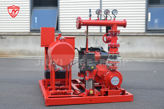
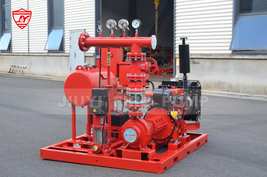
In a fire protection system, every detail is designed to ensure water is available when it’s needed most—during a fire emergency. One critical yet often overlooked component is the fire pump bypass line. Although it might seem like a simple piece of piping, the bypass line plays a vital role in ensuring system reliability, operational flexibility, and compliance with NFPA 20 standards.
This article explains what a fire pump bypass line is, its purpose, how it is configured, and why it is essential for the safety and functionality of fire protection systems.

A fire pump bypass line is a pipeline that provides an alternate route for water to flow directly from the water supply to the fire protection system, bypassing the fire pump itself.
In normal operation, water flows through the fire pump to achieve the necessary pressure and flow required by the sprinkler or hydrant system. However, in some situations—such as pump maintenance, repair, or failure—the bypass line ensures that water can still reach the fire protection system, even without the pump in operation.
In short, the bypass line acts as a redundant safeguard for continuous water delivery in case the fire pump becomes unavailable.
The installation and design of fire pump bypass lines are governed by NFPA 20, the Standard for the Installation of Stationary Pumps for Fire Protection. According to NFPA 20, a bypass line must be installed when the water supply is capable of providing adequate flow and pressure directly to the system without pump assistance.
Key NFPA 20 recommendations include:
The bypass line must be sized to supply at least the same flow as the fire protection demand, if possible.
It must include valves and fittings to control and isolate the bypass.
The bypass should be readily accessible for maintenance and testing.
The line must be connected in such a way that water can reach the fire protection system even if the fire pump is not in service.
These design standards ensure that fire protection remains operational even during pump outages or maintenance periods.
The core purpose of a fire pump bypass line is to maintain water supply continuity to the fire protection system when the pump is unavailable. Below are the main functions explained in detail:
If the fire pump is shut down for maintenance or has a mechanical failure, the bypass line allows water to flow directly from the water source—such as a city main or gravity tank—into the sprinkler or hydrant system. This ensures that firefighting water supply is never interrupted, providing a critical safety net.
Maintenance is essential for the reliability of fire pumps. However, shutting down the pump should not compromise fire protection coverage. The bypass line enables technicians to service or inspect the pump while the building remains partially protected through the bypassed water flow.
In some testing scenarios, operators can use the bypass line to simulate flow conditions or verify system operation without engaging the fire pump.
Additionally, in an emergency where the pump controller or power supply fails, the bypass line acts as a manual emergency water route.
In systems where water supply pressure fluctuates, the bypass line can help balance flow and prevent overpressure conditions. It can also allow limited flow to the system when full fire pump operation is unnecessary, such as during low-demand conditions or testing.
A well-designed bypass line typically includes the following components:
Used to control whether water flows through the bypass line. During normal operation, these valves are closed. They are opened only when bypass operation is needed.
Installed to prevent backflow into the water supply or pump suction line. This ensures water only moves in the correct direction—from the supply toward the system.
Allow operators to monitor water pressure on both sides of the bypass line, helping verify performance and detect potential issues such as pressure loss or blockage.
Some installations include flow meters for testing and monitoring the bypass line capacity.
The size and material of the piping depend on the fire protection system design, pressure rating, and local standards. Typically, carbon steel or ductile iron piping is used.
The typical configuration of a fire pump bypass line involves a connection from the incoming water supply (before it enters the pump suction) directly to the system discharge piping (downstream of the pump discharge).
This means the bypass line “bridges” across the pump, providing a direct path for water. The line usually includes:
An isolation valve on both ends for control
A check valve to prevent reverse flow
Pressure gauges for monitoring
Depending on system requirements, the bypass line can be manually operated or designed to open automatically under certain pressure conditions.
Not every fire pump installation requires a bypass line. According to NFPA 20, a bypass line is only necessary when the water supply alone can provide sufficient pressure and flow to meet part or all of the system demand.
Common examples where bypass lines are installed include:
City water-fed systems, where supply pressure is usually adequate for sprinkler operation
Systems with reliable gravity tanks
Dual water supply systems that can function independently of the fire pump
However, in systems that rely entirely on the pump for pressure—such as those drawing from storage tanks or suction reservoirs—bypass lines may not be applicable or beneficial.
Enhanced System Reliability
Provides an additional layer of protection in case of pump or power failure.
Operational Flexibility
Allows for maintenance and testing without disabling the entire fire protection system.
Improved Safety Compliance
Meets NFPA 20 and insurance requirements for redundant water delivery paths.
Quick Response in Emergencies
In the event of electrical or mechanical pump failure, the bypass line can still deliver water to critical areas.
Cost-Effective Backup Solution
Compared to installing a secondary fire pump, the bypass line is a simpler and more economical redundancy measure.
Even though the bypass line seems straightforward, improper design or installation can compromise its function. Some common mistakes include:
Undersized piping, which limits flow capacity
Incorrect valve placement, preventing full bypass functionality
Lack of check valves, leading to backflow issues
No pressure monitoring, making performance verification difficult
Failure to test periodically, causing undetected blockages or valve seizure
Proper design, according to NFPA 20 guidelines and manufacturer recommendations, is essential for ensuring the bypass line performs effectively when needed.
Like all components of a fire protection system, the bypass line requires regular inspection and maintenance. Here are best practices to ensure reliability:
Visual Inspection: Check for leaks, corrosion, and valve position monthly.
Valve Operation Test: Verify that isolation valves open and close smoothly.
Pressure Test: Measure inlet and outlet pressure to confirm flow capacity.
Functional Test: Periodically simulate a bypass condition to ensure water can flow freely through the line.
Documentation: Record all inspections and tests as required by NFPA 25 for system maintenance compliance.
Regular maintenance helps ensure that the bypass line will function correctly in an emergency situation.

A fire pump bypass line may appear to be a small component, but its role is crucial in maintaining fire system reliability and compliance with NFPA 20 standards. By providing an alternate water route, it ensures that fire protection systems remain operational even when the pump is offline—protecting property and lives from unnecessary risk.
For building owners, engineers, and maintenance teams, understanding and maintaining this line is not just a matter of regulation—it’s a vital part of a well-designed fire safety system.