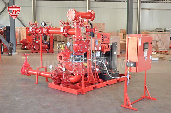
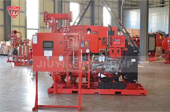
Setting up your fire pump controller correctly is critical for ensuring your fire protection system works flawlessly when needed. A well-configured controller enhances system reliability, reduces false alarms or failures, and prolongs equipment life. This article walks you through a structured, step-by-step process—covering design standards, wiring, commissioning, testing, maintenance, and diagnostics—so you can confidently optimize your installations for reliable operation.

Know applicable standards: Ensure compliance with NFPA 20 (“Standard for the Installation of Stationary Pumps for Fire Protection”) and NFPA 25 (“Standard for the Inspection, Testing, and Maintenance of Water-Based Fire Protection Systems”).
System specifics matter: Confirm desired pump type (e.g., diesel, electric), power sources, and the interface with supervisory systems (e.g., building management or fire alarm systems).
Controller rating & environment: Choose controllers rated for your voltage, ambient conditions, enclosure classification (e.g., NEMA 1 vs. NEMA 4X), and anticipated duty cycles.
Redundancy & monitoring needs: Determine if automatic switchover, remote annunciation, or dual-controller setups are needed; plan for isolation between power sources (e.g., utility vs. standby generator).
Mounting location: Install the controller in a clean, accessible, dry, and temperature-controlled space, close to the pump but isolated from vibration and corrosive conditions.
Power wiring best practices: Use correctly rated conductors, proper gland and conduit seals, and keep power and signal wiring separate to prevent electrical interference.
Grounding & bonding: Implement robust grounding per local electrical codes and manufacturer guidelines to reduce electrical noise and protect against surges.
Signals & connections: Label all terminal blocks clearly (e.g., “Flow Switch,” “Pressure Transducer,” “Fire Alarm Input,” “Remote Annunciation”), and keep spare space for future expansion.
Surge protection: Install surge protective devices (SPDs) on power and signal lines to shield sensitive electronics from lightning or switching surges.
Set control logic parameters:
Start thresholds: Define low pressure or flow switch setpoints as per design.
Delay timers: Configure minimum run times, start-up delays, and off-delays to avoid nuisance restarts or cycling.
Stop criteria: Ensure stopping logic includes adequate cooldown or pressure recovery time.
Alarm thresholds & annunciation: Clearly define high/low pressure, over-current, phase-loss, and other fault thresholds with corresponding alarms and status lights/sounds.
Communication settings:
Configure for SCADA/BMS interfaces using Modbus, Ethernet/IP, or relevant protocols.
Set correct network addressing and polling rates to minimize latency.
Security and access control: Protect settings via user levels, passwords, or physical locks to prevent unauthorized changes.
Documentation: Record all configuration values and calibrations in a commissioning log and make them part of the “as-commissioned” documentation package.
Initial dry-run: Power up and check basic functionality: indicator lights, control logic, manual start/stop buttons, and fault conditions.
Wet-test under load:
Run the pump with normal supply pressures and loads.
Confirm proper automatic start on low pressure or flow, and safe, controlled stop.
Watch for oscillations, false trips, or abnormal vibration/temperature.
Simulate fault conditions:
Trigger low-pressure or flow fault and verify correct alarm and auto-start sequence.
Simulate phase loss, over-current, or power loss to validate safe shutdown or backup switchovers.
Data logging & monitoring: Use handheld loggers or SCADA to record key metrics (e.g., current draw, pressure trends, start time) for analysis.
Annunciation tests: Confirm remote signals by testing fire alarm panel integration, door station signals, and BMS dashboards with correct status and priority.
Acceptance testing & sign-off: Ensure you follow the owner's or authority having jurisdiction’s acceptance form, complete checklists, and document all findings, deviations, and corrections.
Periodic inspection: Perform visual inspections of controller wiring, enclosure seals, and cleanliness.
Functional testing schedule: As per NFPA 25, test key functions (e.g., fire alarm interlock, low-pressure start, supervisory signals) monthly and annually.
Update firmware & patches: Keep firmware up-to-date to fix bugs and improve performance, following manufacturer’s guidelines.
Battery and backup checks: For controllers with internal batteries or UPS, check battery health, replace aged batteries, and test failover.
Calibration verification: Annually check and recalibrate pressure sensors, flow switches, and current transformers to ensure setpoints haven’t drifted.
Recordkeeping: Log all tests, calibrations, and anomalies. This documentation supports regulatory compliance and helps diagnose recurring issues more efficiently.
Built-in diagnostics: Leverage controllers with self-test features (e.g. load test, self-check) to highlight issues before failure.
Remote monitoring integration: Use modern controllers that support cloud-based or networked dashboards for real-time alarm push notifications, historical trend graphs, and system health alerts.
Predictive maintenance: Analyze vibration, motor current, running hours, and start counts to predict and plan maintenance before a failure occurs.
Training & remote access: Equip operators with login-based access to view status, metrics, or remote-assist technicians troubleshooting configuration or alarms.
| Phase | Key Actions |
|---|---|
| Planning | Review NFPA, define requirements, allow redundancy |
| Installation | Proper wiring, labeling, grounding, surge protection |
| Configuration | Set thresholds, timers, communication, security |
| Commissioning | Dry/wet testing, simulate faults, document and sign-off |
| Maintenance | Regular testing, calibration, battery health, logs |
| Monitoring | Use diagnostics, remote monitoring, trend analysis |

A fire pump controller is the central nerve of your fire protection pump system. Its proper setup touches design, wiring, parameter tuning, commissioning, testing, and proactive upkeep. By following these structured steps—grounded in NFPA standards—you’ll optimize your controller for dependable, long-term operation and ease of maintenance. The upfront investment in accuracy, testing, and documentation delivers dividends in resilience, fewer nuisance responses, enhanced safety, and regulatory peace of mind. Contact us to learn how our controller solutions can support best-in-class reliability tailored to your projects.