In a fire protection system, every detail matters — and the rotation direction of your fire pump is one of the most critical. Installing a pump that rotates in the wrong direction can lead to severe performance issues, mechanical damage, and even complete system failure during an emergency. Whether you’re working with an electric motor-driven or diesel engine-driven fire pump, verifying the correct pump rotation before startup is essential.
This article will guide you through understanding what pump rotation means, how to identify it correctly, and why getting it right is crucial for fire safety.
Pump rotation direction refers to the rotational movement of the pump’s impeller when viewed from a specific point — usually from the driver (motor or engine) end. In most fire pumps, the direction can be clockwise (CW) or counterclockwise (CCW).
The rotation determines how the impeller pushes water through the casing, directly affecting pressure, flow, and overall pump efficiency. If the impeller rotates in the wrong direction, the pump will not produce the designed discharge pressure and may cause overheating, seal damage, and vibration.
Incorrect pump rotation can cause more than just performance issues. Below are the key reasons why ensuring the correct direction is vital:
Performance and Efficiency
A pump rotating in the wrong direction will fail to generate the correct head and flow rate. In a fire emergency, this could mean insufficient water delivery to the sprinkler system or hydrants.
Mechanical Damage
Reverse rotation may damage the impeller, mechanical seals, bearings, and coupling due to abnormal forces acting on components designed for one-directional flow.
Motor and Engine Protection
Electric motors and diesel engines are designed to drive the pump in a specific direction. Reversing rotation can cause overload or coupling misalignment.
Compliance and Safety
NFPA 20 and UL standards emphasize proper installation and testing of fire pump systems, including rotation checks, to ensure compliance and system reliability.
Every fire pump manufacturer specifies the correct rotation direction on the pump casing or nameplate. Here are the main ways to identify it:
Pump Casing Arrow
Most centrifugal fire pumps have a cast arrow on the pump casing showing the intended direction of shaft rotation or water flow. This is the most straightforward visual indicator.
Manufacturer’s Nameplate or Documentation
The data plate on the pump or driver usually includes rotation direction, model number, and performance data. Always cross-check with the manufacturer’s installation manual.
Impeller Orientation
The impeller design itself dictates flow direction. When viewed from the suction end, a right-hand (clockwise) impeller will discharge water to the right, while a left-hand (counterclockwise) impeller will discharge to the left.
Pump Type and Layout
The rotation direction may also depend on the pump type (horizontal split case, end suction, vertical turbine, etc.) and whether it’s a direct-coupled or right-angle drive setup.
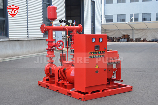
For electric motor-driven fire pumps, rotation is typically easier to verify than for diesel engines. Here’s how:
Check Motor Rotation Arrow
The electric motor will usually have a rotation arrow stamped or labeled near the shaft end.
Jog the Motor
Before coupling the motor to the pump, briefly “jog” the motor by energizing it for a second or two to observe shaft rotation. This should always be done without water pressure and without the coupling connected.
Compare with Pump Rotation Arrow
Verify that the motor’s observed rotation matches the pump’s designated direction. If they are opposite, reverse any two leads on the motor’s power supply (for three-phase motors).
Re-Test Before Coupling
After changing the leads, jog the motor again to confirm the correct direction. Once verified, the coupling can be connected, and alignment checked.
Important Note: Never test rotation with the coupling connected on an unverified setup — it may damage both the pump and motor if rotation is wrong.
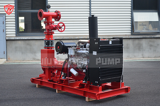
For diesel engine-driven fire pumps, the process is slightly different because diesel engines have fixed rotation directions based on their design.
Check the Engine Nameplate
Diesel engine manufacturers clearly mark rotation direction as viewed from the flywheel end. It can be clockwise (CW) or counterclockwise (CCW).
Check the Pump’s Required Rotation
Compare this with the fire pump’s specified rotation as viewed from the coupling end.
Use Gear Drives if Needed
If the engine and pump rotations do not match, a right-angle gear drive can be used to change the rotation direction to suit the pump.
Test During Commissioning
During system commissioning, always perform a slow-speed test to confirm correct rotation before full-speed operation.
Even experienced installers can overlook simple details that lead to incorrect rotation. Below are common mistakes to avoid:
Assuming direction without checking arrows or nameplates.
Skipping jog tests before coupling motor and pump.
Confusing view direction (pump end vs. driver end).
Not verifying after electrical wiring changes.
Ignoring vertical turbine configurations, where driver and impeller are vertically aligned and rotation can be counterintuitive.
By following a systematic verification process, these errors can be avoided easily.
End Suction Fire Pumps
Usually rotate clockwise when viewed from the driver end. The discharge nozzle is typically on the right-hand side when facing the suction inlet.
Horizontal Split Case Fire Pumps
Can be either clockwise or counterclockwise depending on the casing design. Always refer to the manufacturer’s arrow or installation guide.
Vertical Turbine Fire Pumps
Usually rotate counterclockwise when viewed from above the driver. However, the column assembly design may alter this, so always verify during installation.
Inline Fire Pumps
Commonly driven by electric motors directly mounted above or below the casing. Rotation follows the motor’s standard direction (clockwise).
Operating a fire pump in reverse rotation, even briefly, can have damaging consequences:
Reduced or zero water discharge
High vibration and noise
Seal or bearing damage
Coupling failure
Cavitation and overheating
Voiding of manufacturer warranty
That’s why checking and confirming rotation before first startup is not optional — it’s an essential step for any fire pump installation.
To ensure consistency and safety in future maintenance, consider the following best practices:
Mark the Direction Clearly
Use a permanent arrow or tag showing correct rotation near the coupling or driver.
Include Rotation in Commissioning Reports
Always document observed rotation and test results as part of your system startup record.
Train Installation Teams
Ensure all technicians understand how to determine and confirm pump rotation correctly.
Conduct Routine Checks
If any electrical or mechanical maintenance occurs, recheck the rotation direction before resuming operation.
Determining the correct pump rotation direction is a small but vital step in ensuring the safety, performance, and reliability of your fire protection system. Whether you’re working with an electric motor or a diesel engine, never assume — always verify.
As a professional manufacturer of fire pumps, we emphasize that proper installation and testing procedures protect not only your equipment investment but also lives and property during fire emergencies.
Accurate rotation direction is the foundation of dependable firefighting performance — get it right from the start.